

Rev B · October 2026
Leave this manual with the owner
Molitron Pollution Control Unit (PCU) · Models EPFA-24 to EPFA-144
Installation, Operation & Maintenance Manual
For installing contractors, engineers, and the owners and staff who look after the unit day to day.

Scan or select the mark to verify the UL listing.
- 11models, EPFA-24 to EPFA-144
- 1,800–10,800CFM planning airflow
- 120 VACmonitoring supply
- UL ListedFile MH45752
Contents
- 01About this manual3
- 02Models and filters4
- 03Dimensions and construction5
- 04Installation6
- 05Fire protection7
- 06Controls, wiring and status panel8
- 07Setting the pressure switch11
- 08Maintenance11
- 09Warranty13
- 10Start-up and owner forms14
- 11Engineer’s corner17
Where to start
Owners and kitchen staff
What the lights mean, the four-week filter check, your warranty and the filter service log.
Sections 06, 08, 09, 10
Installing contractors
Placement and clearances, fire-suppression pre-piping, wiring, the pressure switch and the start-up forms.
Sections 04, 05, 06, 07, 10
Engineers
Models and filters, the true-scale drawing sheet and copy-ready specification text.
Sections 02, 03, 11
Record for this unit
- Model
- Serial number
- Ship date
- Start-up date
- Installing contractor
- Contractor’s phone
- Status panel location
- Clean-filter static pressure, in. w.g.

This manual online
Search, step-by-step walkthroughs (the pressure switch setup animated), the zoomable drawing sheet and fill-in forms, at molitron.com/products/epfa/operation-maintenance. Questions or replacement filters: 303-969-8888 · cleanair@molitron.com.
Section 01
About this manual
Important
Installation must be performed by a qualified professional who has read and understands these instructions and is familiar with proper safety precautions. Read this manual before installing or servicing the equipment.
This manual belongs to the owner of the equipment and is needed for future maintenance. Leave it with the owner when installation or service is complete. The owner is responsible for maintaining and servicing the equipment.
What the PCU is
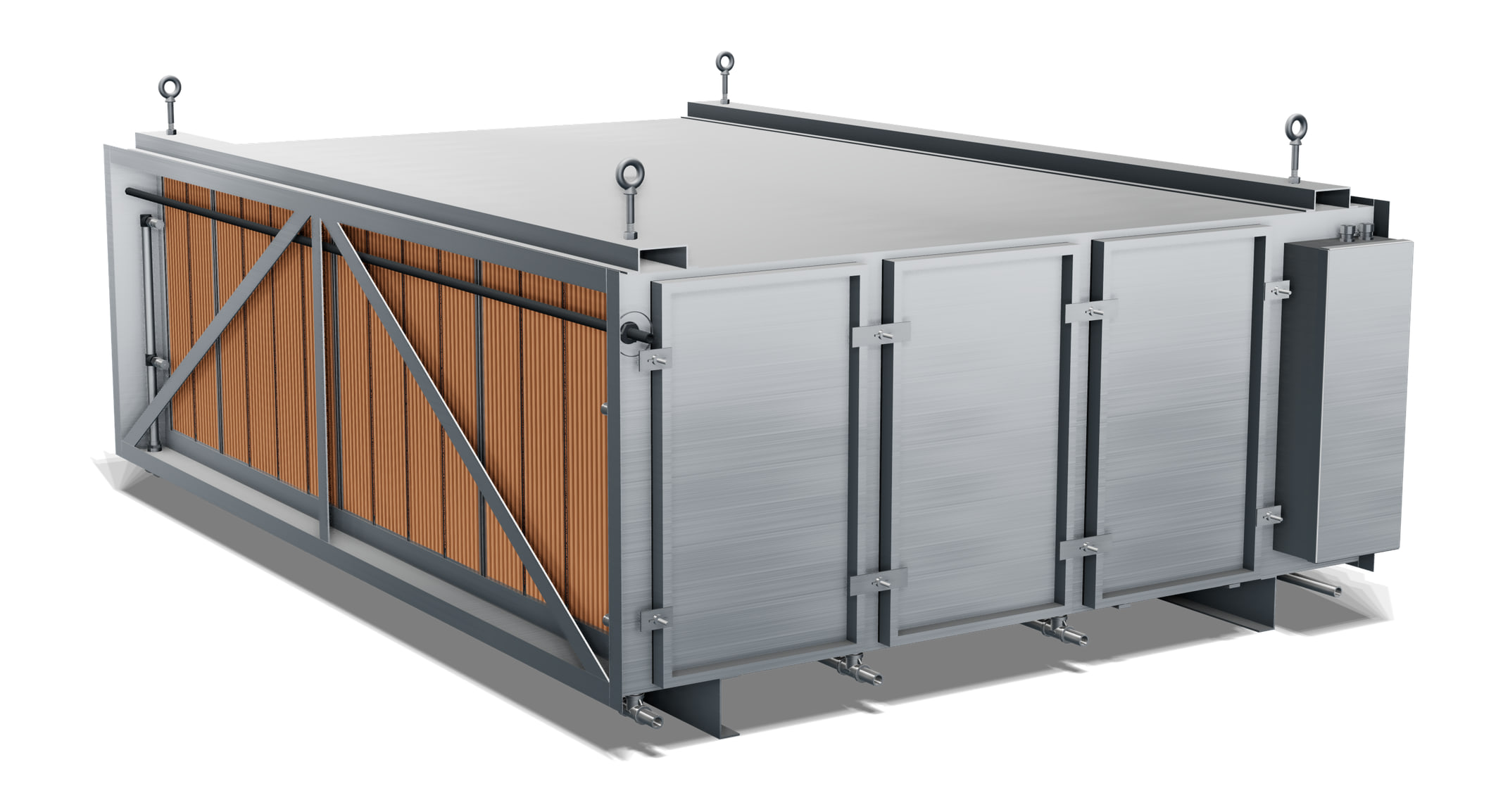
A UL Listed, fully welded 18-gauge stainless-steel enclosure that installs in the grease duct between the kitchen hood and the exhaust fan. Channels hold three rows of filters that remove particulate matter and grease vapor from kitchen exhaust. Removable doors give access to the filters and fire-protection components; a controls enclosure at the outlet end monitors system static pressure and drives a wall-mounted status panel.
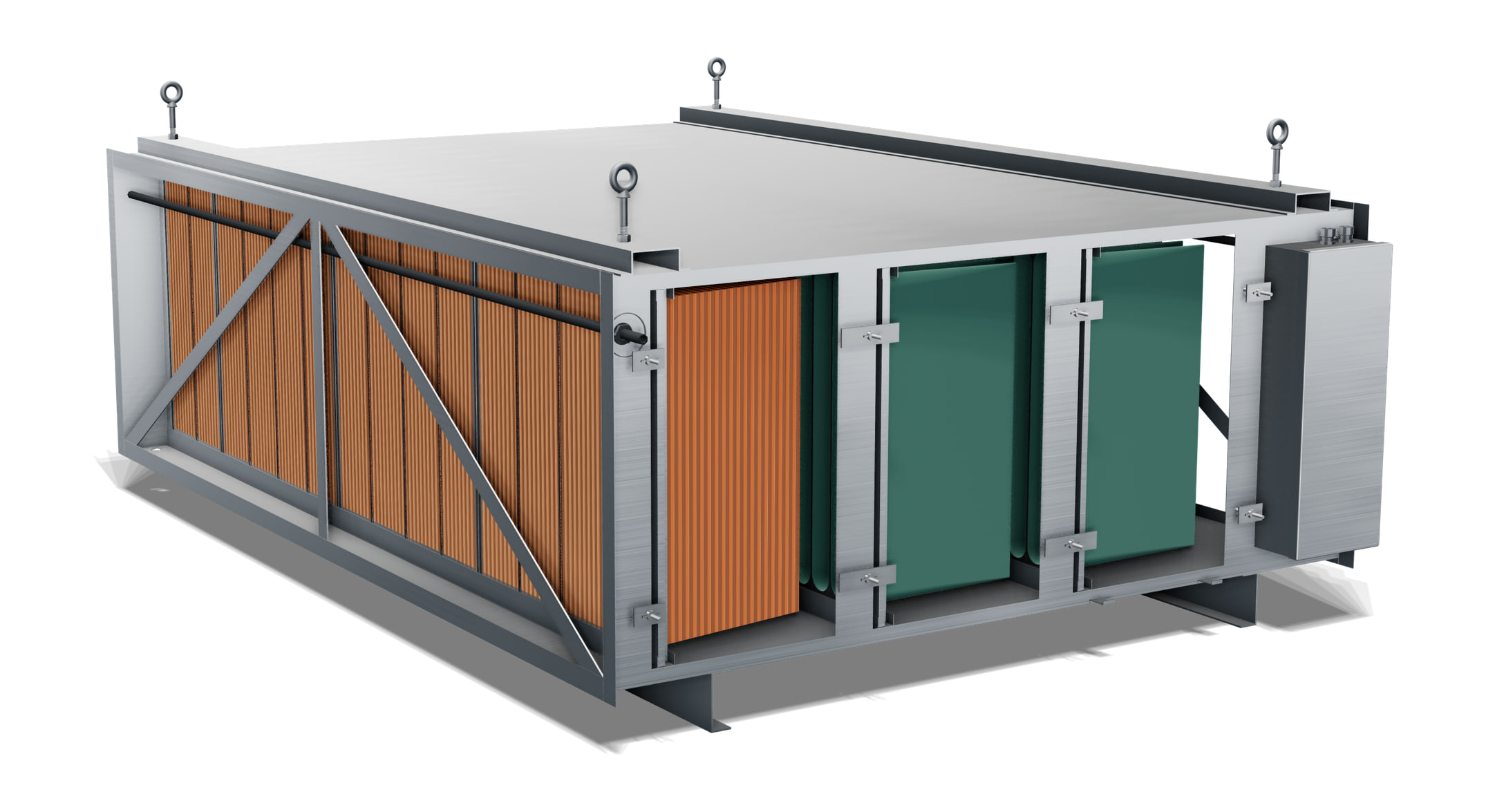
- Inlet end, from the kitchen hood
- Pre-filters, MERV 9 (orange)
- High-efficiency filters, MERV 14 (green)
- High-efficiency filters, MERV 14, or optional carbon
- Static pressure controls enclosure
EPFA-84 with its access doors off, rendered from Molitron’s 3D model.
Section 02
Models and filters
Every model is 63 in. long; the number is the width in inches. Airflow values are for planning.
| Model | Planning airflow, CFM | Width | Approx. weight | Pre-filters | High-efficiency filters | Carbon adds | ||
|---|---|---|---|---|---|---|---|---|
| 24 × 12 | 24 × 24 | 24 × 12 | 24 × 24 | |||||
| EPFA-24 | 1,800 | 24 in. | 250 lb | – | 1 | – | 2 | 72 lb |
| EPFA-36 | 2,700 | 36 in. | 350 lb | 1 | 1 | 2 | 2 | 108 lb |
| EPFA-48 | 3,600 | 48 in. | 450 lb | – | 2 | – | 4 | 144 lb |
| EPFA-60 | 4,500 | 60 in. | 550 lb | 1 | 2 | 2 | 4 | 180 lb |
| EPFA-72 | 5,400 | 72 in. | 650 lb | – | 3 | – | 6 | 216 lb |
| EPFA-84 | 6,300 | 84 in. | 750 lb | 1 | 3 | 2 | 6 | 252 lb |
| EPFA-96 | 7,200 | 96 in. | 850 lb | – | 4 | – | 8 | 288 lb |
| EPFA-108 | 8,100 | 108 in. | 950 lb | 1 | 4 | 2 | 8 | 324 lb |
| EPFA-120 | 9,000 | 120 in. | 1,050 lb | – | 5 | – | 10 | 360 lb |
| EPFA-132 | 9,900 | 132 in. | 1,150 lb | 1 | 5 | 2 | 10 | 396 lb |
| EPFA-144 | 10,800 | 144 in. | 1,250 lb | – | 6 | – | 12 | 432 lb |
Filter sizes are nominal, in inches. Units can be stacked to save floor space; contact Molitron.
Filter rows, inlet to outlet
- F1MERV 9 multi-pocket pre-filter (orange)23.31 × 23.31 × 12 in. (H × W × D)
- F2MERV 14 multi-pocket high-efficiency filter (green)23.31 × 23.31 × 12 in. (H × W × D)
- F3MERV 14 multi-pocket high-efficiency filter (green), or optional carbon filter23.31 × 23.31 × 12 in.; carbon 23.375 × 23.375 × 12 in. (H × W × D)
Half-size pre-filters and high-efficiency filters (24 × 12 nominal) are 23.31 × 11.31 × 12 in. (H × W × D). The filters sit in 1-in.-wide welded T304 channels (top, bottom and back side), sealed to the outer skin with high-temperature silicone.
Section 03
Dimensions and construction
- 63-inch length. Every model is 63 in. long in the direction of airflow. Width W is the model number: an EPFA-84 is 84 in. wide.
- Filter channels. Welded 1-in. stainless channels hold the three filter rows. From the inlet end: F1 at 4 in., F2 17 in. further, F3 17 in. beyond that, then 25 in. to the outlet end.
- Access doors. Three removable 18-gauge stainless access doors, gasketed, on the service side. Doors on both sides are optional.
- Static pressure controls enclosure. At the outlet end, with a removable gasketed cover: the 120 VAC junction box and 120/24 VAC transformer, the static pressure gauge, two pressure switches and the wiring terminal block.
- Duct flange. A 1.5-in. flange around the full perimeter of each end, for welding to the connecting ductwork (by others).
- Hanger angles. An 11-gauge stainless hanger angle welded at each top corner, with a 1/2-13 threaded hole. Its removable galvanized eyebolt (1/2-13, 1-7/8 in. thread) is for lifting and positioning only. Hang the unit on spring hangers with separate upper and lower threaded rods; the hangers, rods and hardware are by others, and the project’s designer or installer selects the rod size, the hangers’ rated load and the anchorage.
- Bottom rails. Two full-width stainless T304 channels, 1.5 × 4 in. with 1/8-in. wall, welded to the bottom 8 in. in from each end.
- Cleaning drains. Three 1-1/2 in. stainless FPT couplings in the bottom, 13, 30 and 51 in. from the inlet end, as dimensioned in the plan. Connect them to a common 2-1/2 in. drain routed to the grease interceptor (by others).
Section 04
Installation
- Location
- In the grease duct between the kitchen hood and the exhaust fan, indoors or outdoors, in an accessible location.
- Direction
- Inlet end from the kitchen, outlet end toward the exhaust fan.
- Duct connections
- Welded to the exhaust duct at each end, using the 1.5-in. perimeter flange.
- Inlet duct
- Provide straight duct on the inlet side of at least 3 times the duct diameter, to avoid system effect.
- Exhaust fan
- UL Listed for kitchen exhaust, backward-inclined utility type, with easily adjustable RPM. The PCU’s initial (clean-filter) resistance is 1.54 in. w.g.; size the fan for 2.5 in. w.g. plus hood and duct static losses.
- Rooftop support
- The two 4-in. stainless bottom channels support the unit across its full width. The installing contractor provides a code-approved roof curb.
- Indoor suspension
- Suspend the unit from its four hanger angles on spring hangers, with separate upper and lower threaded rods; the hangers, rods and hardware are by others. The project’s designer or installer selects the rod size, the hangers’ rated load and the anchorage. The removable eyebolts are for lifting and positioning only, not for hanging the unit.
- Service side
- At least 30 in. of free space between the access doors and any adjacent wall.
- Other sides
- At least 18 in. to combustible materials and building insulation, or zero clearance to noncombustible materials.
- Above a ceiling
- A permanent platform (by others) is required for servicing every four weeks, at the same height as the bottom of the unit.
- Drains
- Connect the three 1-1/2 in. cleaning drains to a common 2-1/2 in. drain and route it to the grease interceptor (by others).
- Codes
- Install and use only in accordance with these instructions. The installing contractor is responsible for local code requirements.
Section 05
Fire protection
Molitron provides fire-suppression pre-piping: the PCU comes piped to its fire-suppression nozzles, ready for the fire-protection installer to connect. ANSUL is one brand option, and other customer-selected brands are supported.
The PCU does not connect to the building sprinkler system.
Fire-suppression design and approval are project-specific. Confirm the pre-piping on the project’s submittal drawing.
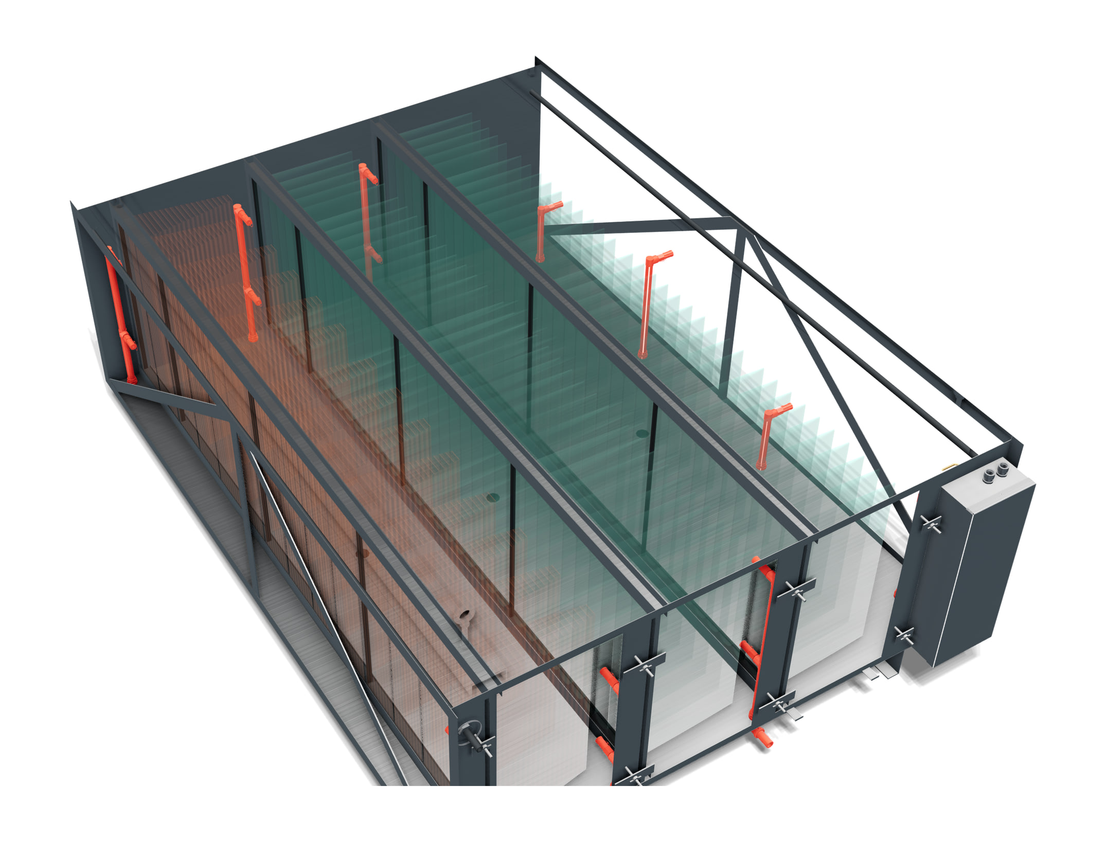
The pre-piping in red, with the top cut away, the doors off and the filters faded back. Rendered from Molitron’s 3D model of the EPFA-84; the pipework is illustrative.
- Field responsibilities
- The fire-protection installer is responsible for the final hook-up, permits, drawing submittals and final testing, and provides the tanks, agent, piping from the tanks to the pre-piped nozzles, regulated actuators, cartridges and related components.
- Detection
- The detectors are mechanical fusible links, not electric.
Section 06
Controls, wiring and status panel
Danger: risk of electric shock
Disconnect power before servicing. The junction box in the controls enclosure carries 120 VAC.
Static pressure controls enclosure
At the outlet end of the unit, behind a removable gasketed cover. A 120 VAC supply from the building electrical panel (by others) enters a junction box and powers a 120/24 VAC transformer. Everything after the transformer runs at 24 VAC.
- High static switch adjustment
- The ringed hole in the instruction label, over switch E’s brass adjusting port.
- Static pressure gauge
- Shows total system static pressure, 0 to 10 in. w.g.
- Wiring terminal block
- The field cable to the status panel lands on the top of the block: 1 Common (white), 2 Black (green light), 3 Red (red light). The bottom takes the factory wiring from the switches.
- Fan-on air switch
- Closes when static pressure reaches 1.5 in. w.g., and the green light turns on.
- High static pressure air switch
- Fed through switch D. Closes when static pressure reaches its setting, and the red light starts blinking beside the green.
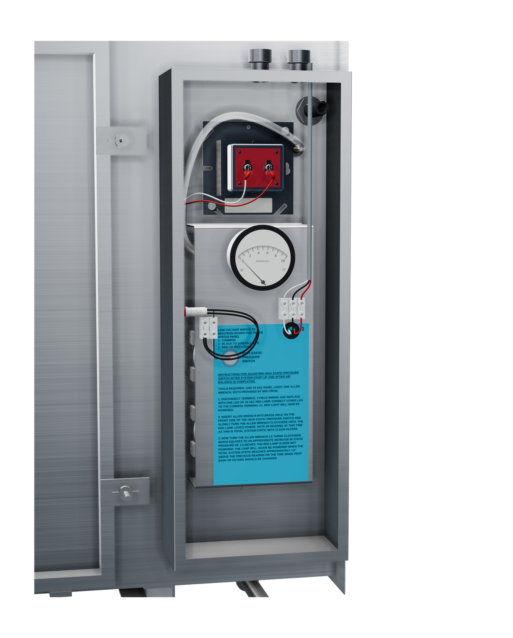
The controls enclosure with its cover off. Molitron provides the 24 VAC test lamp and an Allen wrench for setting switch E.
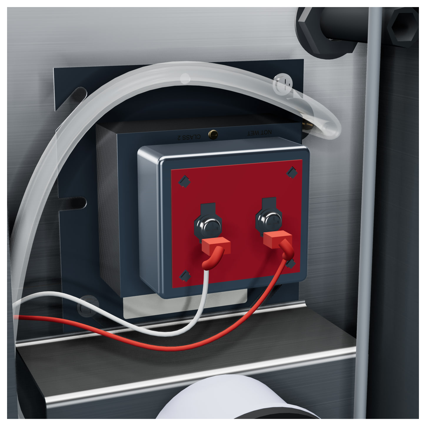
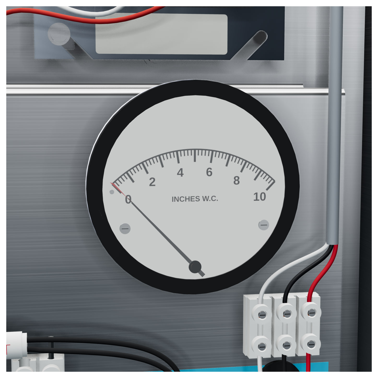
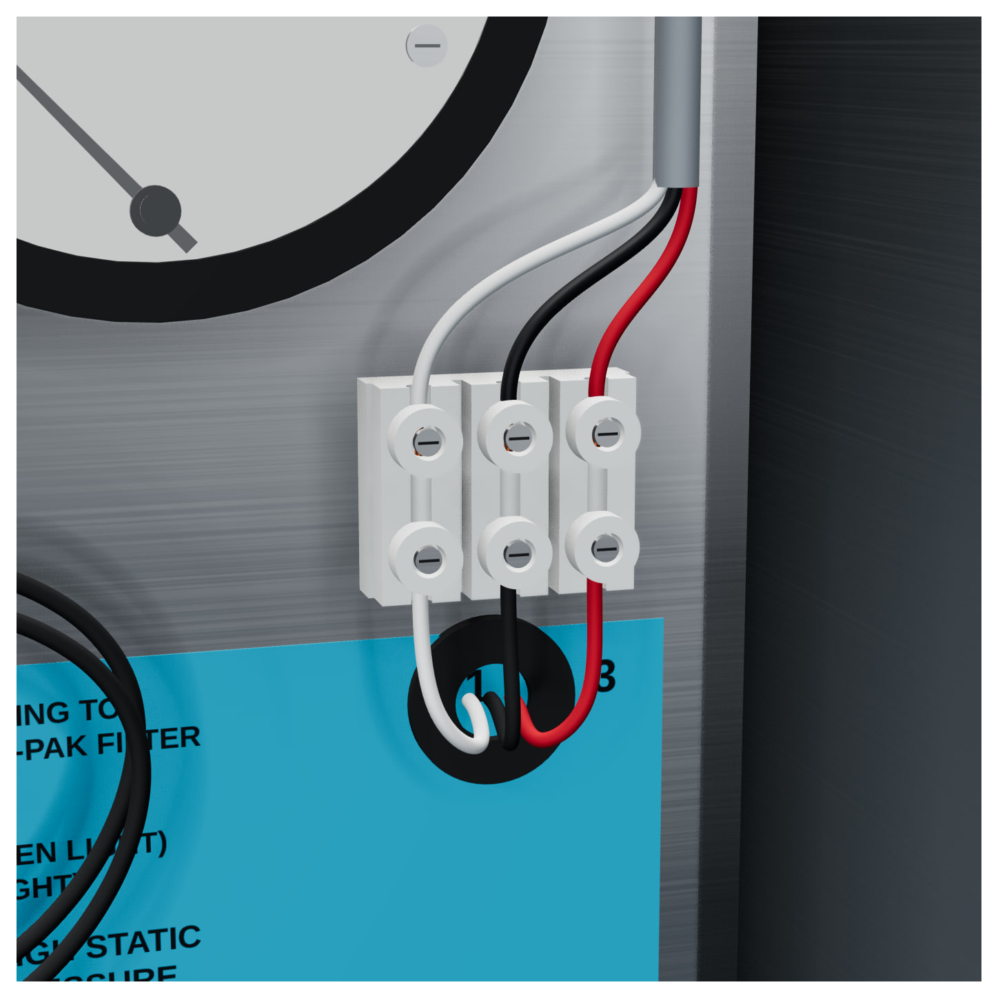
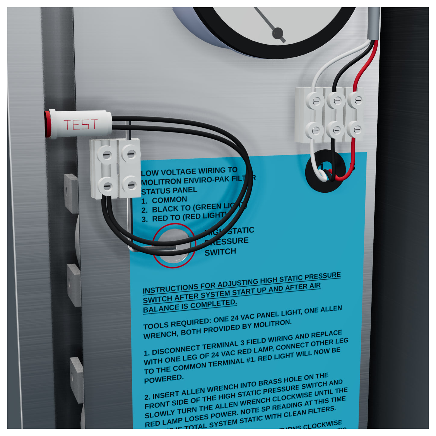
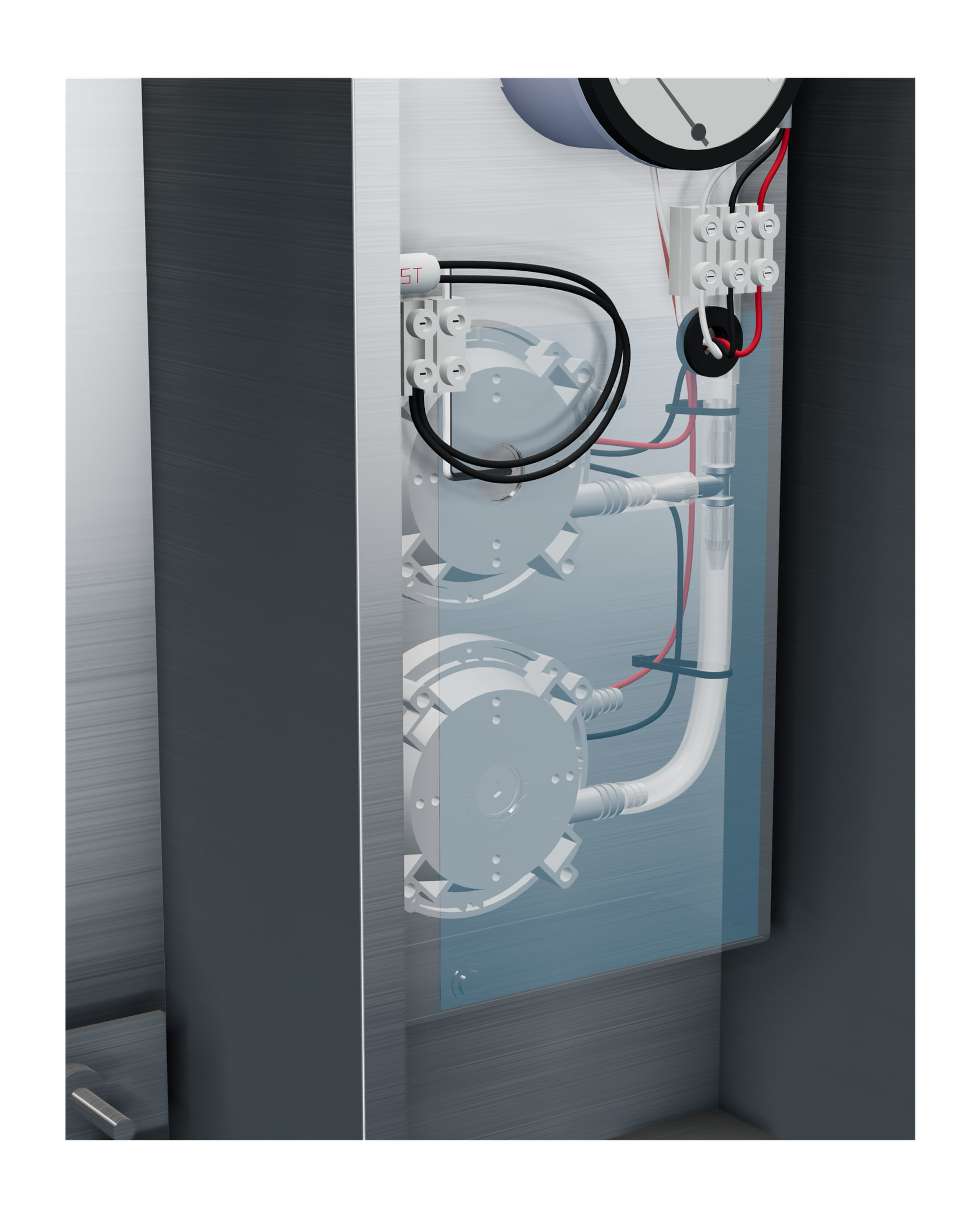
The instrument panel and its label shown clear: fan-on switch D below, high static switch E above, its brass adjusting port behind hole A.
Wiring
One 3-wire 18-gauge plenum cable runs from terminal block C to the status panel, terminal for terminal. The cable, the 120 VAC supply and their connections are by others.
| Terminal | Wire | At the status panel |
|---|---|---|
| 1 · Common | White | Common to both lights |
| 2 · Green light | Black | Green light: exhaust fan on |
| 3 · Red light | Red | Red light, through the flasher: service required |
Switch E is fed through switch D, so the red light can only come on while the exhaust fan is running.
- White, terminal 1: Common
- Black, terminal 2: green light
- Red, terminal 3: red light
- Factory wiring
- 120 VAC supply
- Fan off. Static pressure is below 1.5 in. w.g., so switch D stays open. The transformer holds 24 VAC at D, and both lights are off.
- Fan on. The exhaust fan builds static pressure past 1.5 in. w.g. and switch D closes: the fan is on. 24 VAC reaches terminal 2 and the green light comes on. D also feeds switch E.
- Filter warning. With the fan on, static pressure rises as the filters load until it reaches switch E’s setting and E closes. 24 VAC reaches terminal 3 and the flasher blinks the red light beside the green: service is needed now.
Status panel and its lights
The Molitron Enviro-Pak Filter Status Panel: a factory-furnished, factory-wired stainless enclosure, 12 in. wide, 8 in. high and 2-5/8 in. deep, with a green and a red light. Terminals 1, 2 and 3 on its back match terminal block C. A flasher inside makes the red light blink. Mount it indoors where it can be watched every day; the kitchen or an office is suggested.
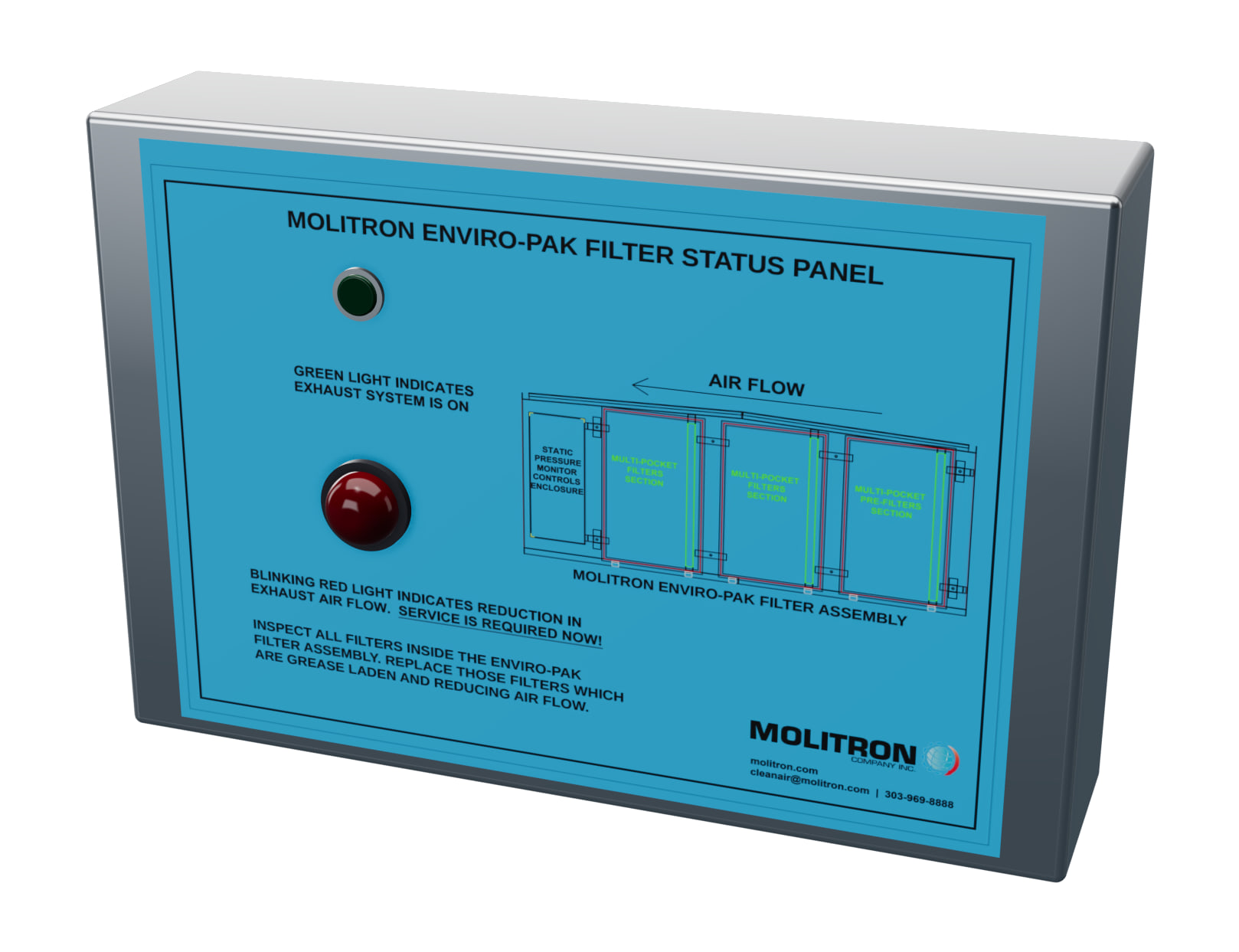
Both lights off: the exhaust fan is off.
With the fan off, switch D is open and neither light has power.
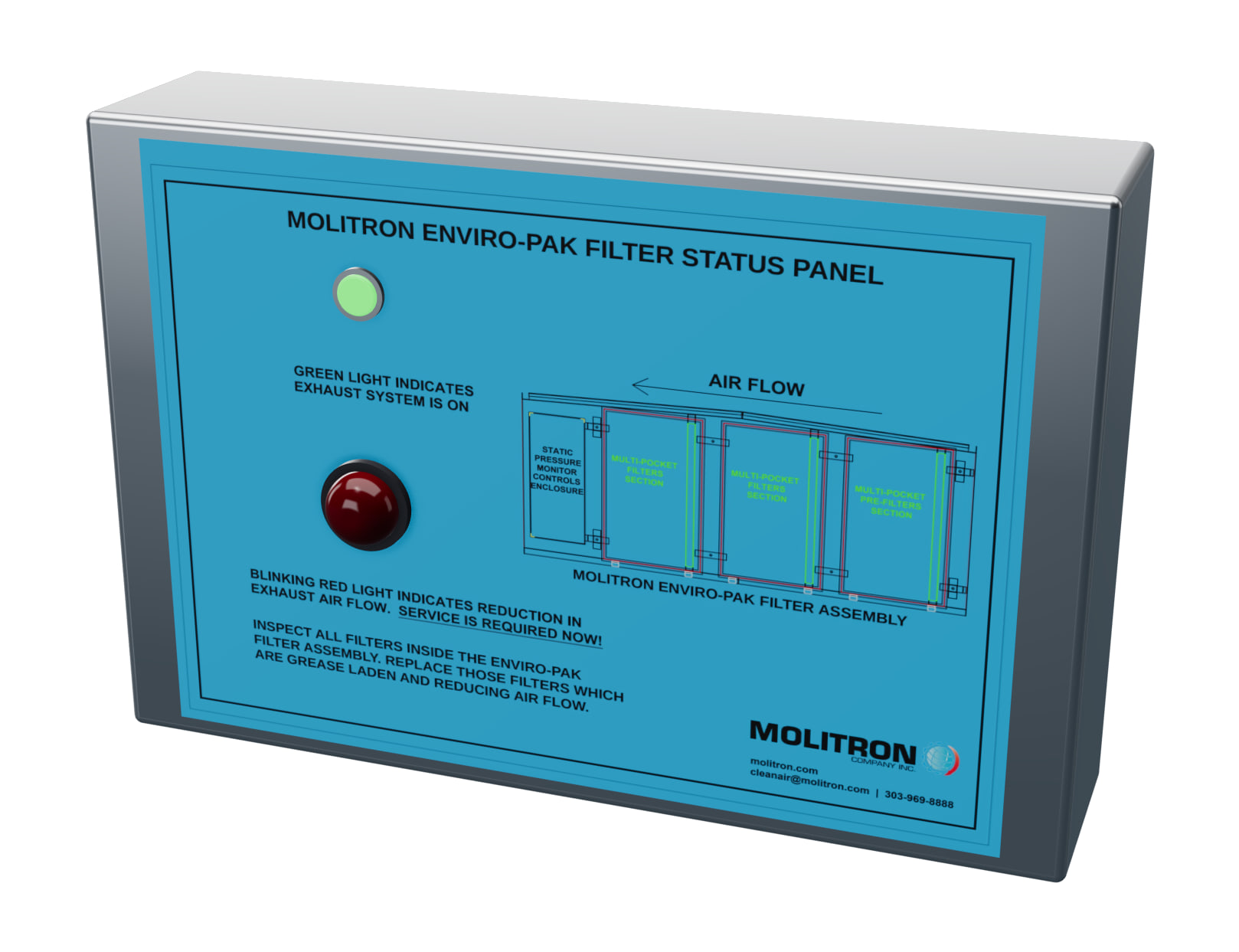
Green light: the exhaust fan is on.
Normal running. Nothing to do but keep to the four-week filter inspection.
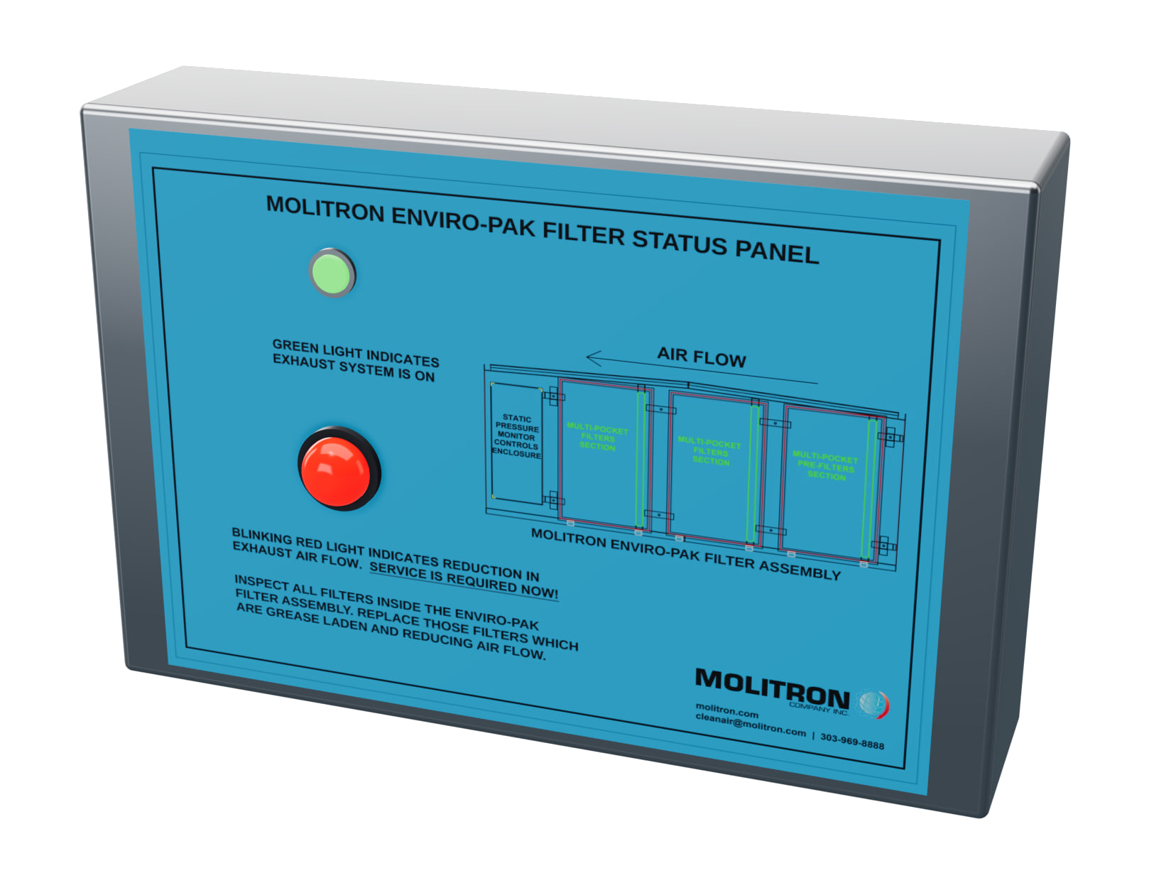
Green and blinking red: service is needed now.
Static pressure has reached switch E’s setting. Inspect every filter and replace any that are loaded with grease and restricting airflow.
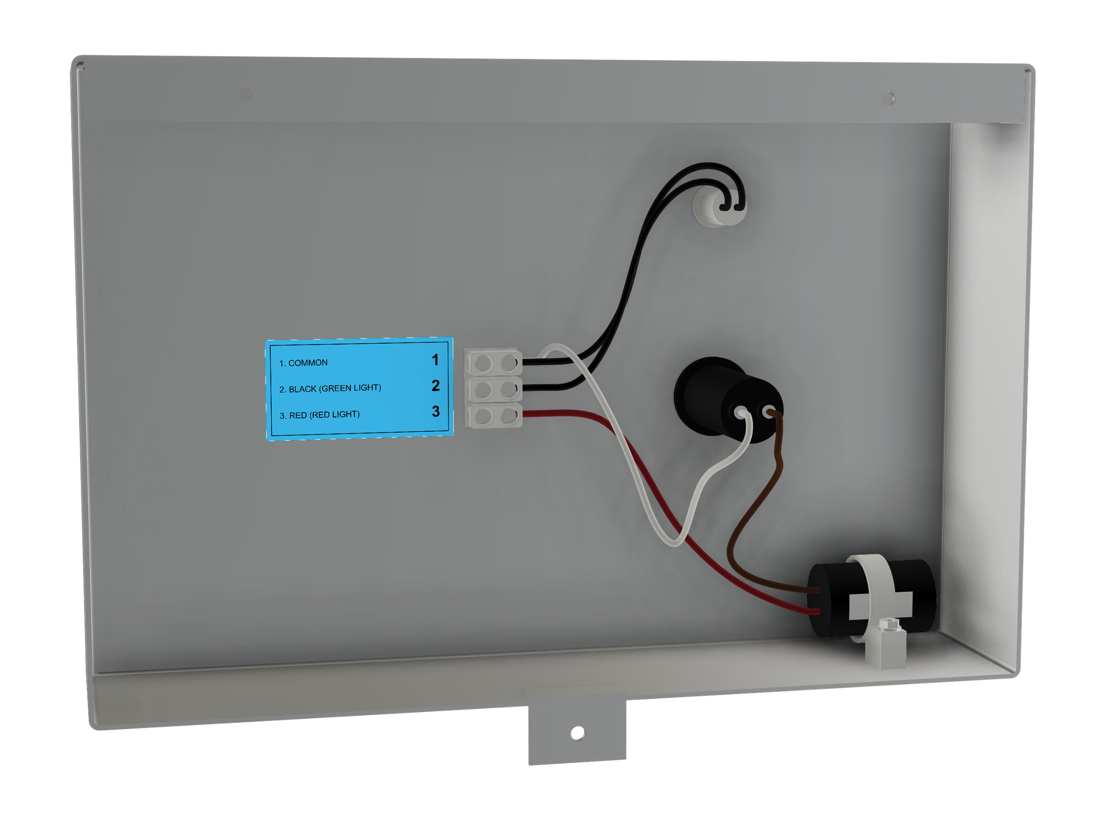
The back of the status panel, from Molitron’s 3D model.
The red light can blink only while the green light shows the fan is on: switch E is fed through switch D.
Section 07
Setting the pressure switch
Set high static pressure switch E after system start-up and after air balance is complete. Molitron provides the tools: one 24 VAC panel test lamp and one Allen wrench. Letters and terminal numbers are those of section 06.
- Connect the test lamp
After start-up and air balance, loosen the top of terminal 3 on block C and disconnect the red field wire. Connect one lead of the 24 VAC test lamp to the top of terminal 3 and the other to the top of terminal 1 (Common), beside the white field wire, and tighten both. The lamp lights. Leave it where you can see it and gauge B together.
- Find the clean-filter reading
Insert the Allen wrench through hole A into the brass port on the front of high static switch E. Turn it slowly clockwise until the lamp goes out. Note the reading on gauge B: the static pressure with clean filters. Write it in the record for this unit.
- Add 1.5 turns
Turn the wrench a further 1.5 turns clockwise. The lamp stays out. Remove the test lamp, reconnect the red field wire to the top of terminal 3 and tighten it, then put the lamp and the wrench back on the shipping terminal.
- Simulate weeks of cooking
In service, the green light shows the fan is on. As cooking loads the filters, static pressure on gauge B rises; when it reaches switch E’s setting, the red light blinks beside the green. Inspect the filters then, and replace those that need it. The time-lapse is an illustration: how quickly filters load depends on the kitchen.
Hole A over switch E; the top of terminals 1 and 3 on block C, where the field cable lands; and the test lamp on its shipping terminal.
Section 08
Maintenance
Every four weeks
Inspect and service the filters, and replace any that are loaded with grease and restricting airflow. A blinking red light means service is needed now, whatever the date. Record each visit in the filter service log (section 10).
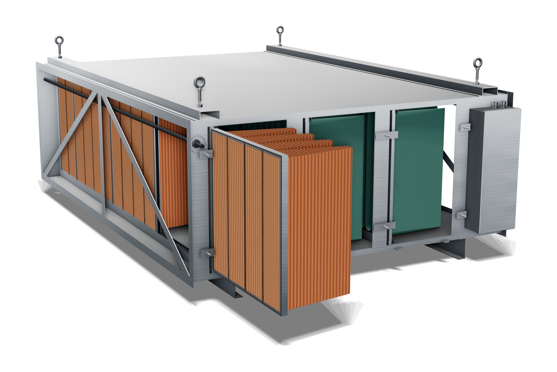
With the doors off, each filter slides out of its channels toward the service side. EPFA-84 shown, with an F1 pre-filter part way out.
- Open the doors
Remove the access doors on the service side.
- Remove used filters
Slide out the filters that are loaded with grease and restricting airflow. Steam-clean the interior if grease has built up.
- Check the gaskets
Each filter takes a 1/4-in. closed-cell neoprene gasket on one vertical side. Green high-efficiency filters come with it fitted; add it to orange pre-filters and to any carbon filter without one. Only one gasket goes between filters: never add a second.
- Install in order
From the inlet: orange pre-filters (MERV 9) in the first row, green high-efficiency filters (MERV 14) in the second, and green high-efficiency filters (MERV 14) or optional carbon filters in the third.
- Push each one home
Push each filter individually into the upper and lower channels, gasketed side first, toward the wall opposite the doors: the first filter’s gasket seals against that wall, and each filter after it seals against the bare side of the one before, one shared seal per joint.
- Close up tight
The last filter’s door-side vertical edge is exposed: add gasket there as needed so the row is tight when the door closes. The damper shields seal the top and bottom of each row. Then seat the doors against their gaskets.
Replacement filters
The owner or the owner’s representative replaces used filters as often as required. Use new filters of the same quality and manufacturer as the original equipment. Molitron accepts no responsibility for visible contaminants escaping the PCU if replacement filters do not match the original specifications or are not installed as described here. Order replacement filters from Molitron: 303-969-8888 · cleanair@molitron.com.
Cleaning
Steam-clean the inside of the PCU to remove any grease buildup.
Section 09
Warranty
The PCU and its component parts, the static pressure controls enclosure and the status panel, are warranted to be free from defects in material and workmanship for 12 months from the date of shipment.
- What’s covered
- A part that proves defective within 12 months is, after examination by the factory, repaired or replaced at no charge for parts. Labor, including installing the replacement part, is not included. Molitron does not accept returns of Molitron products.
- Not covered
- Parts damaged by the freight carrier between the factory and the destination, or by the installing contractor. The factory is not liable for incidental or consequential losses attributable to malfunctioning equipment.
- The warranty does not apply if
- The PCU is not installed by a qualified installer per the factory instructions.
- The PCU is not installed to federal, state and local codes.
- The PCU is misused or neglected.
- The PCU is operated outside its published capacity.
- The invoice is not paid within the terms of the sales agreement.
The warranty is activated once the owner’s acknowledgement (section 10) is signed and returned to the factory. Email a signed copy to cleanair@molitron.com.
Section 10
Start-up and owner forms
Complete the checkoff list before start-up. Return the signed owner’s acknowledgement to Molitron to activate the warranty. Keep the filter service log with this manual.
Section 11
Engineer’s corner
Copy-ready text for a project specification, written from this manual. Edit the model for your project.
PCU — Kitchen exhaust pollution control unit

1. Manufacturer: Molitron Company Inc. Pollution Control Unit (PCU), Model EPFA-[24|36|48|60|72|84|96|108|120|132|144].
2. Listing: UL Listed under File MH45752, investigated to UL 8782, Outline of Investigation for Pollution Control Units for Commercial Cooking Operations.
3. Enclosure: 18-gauge Type 304 stainless steel, fully welded, 63 in. long by model width; 1.5-in. perimeter flange at each end for welded duct connection; full-width sloped top panel; two full-width T304 stainless bottom channels, 1.5 x 4 in.
4. Access: three removable, gasketed 18-gauge stainless access doors on the service side (doors both sides optional).
5. Filtration, in airflow order: F1 MERV 9 multi-pocket pre-filters; F2 MERV 14 multi-pocket high-efficiency filters; F3 MERV 14 multi-pocket high-efficiency filters, or carbon filters where odor treatment is required.
6. Fire protection: factory fire-suppression pre-piping to nozzles, for connection by the fire-protection installer to an ANSUL or other customer-selected system (mechanical fusible-link detectors). A building sprinkler connection is not provided.
7. Drains: three 1-1/2 in. stainless FPT cleaning drain couplings.
8. Monitoring: static pressure controls enclosure with gauge, fan-on and adjustable high static pressure switches, 120/24 VAC transformer; wall-mounted stainless status panel (green: exhaust on; blinking red: service required).
9. Electrical: 120 VAC supply to the unit (by others); 3-wire 18-gauge plenum cable from unit to status panel (by others).
10. Clearances: 30 in. on the service side; 18 in. to combustibles and building insulation on other sides, or zero to noncombustible materials.
11. Exhaust fan (by others): UL Listed for kitchen exhaust, backward-inclined utility type with adjustable RPM. Initial PCU resistance 1.54 in. w.g.; size the fan for 2.5 in. w.g. plus hood and duct static losses.
Listing details: molitron.com/codes-compliance. For drawings or project questions: 303-969-8888 · cleanair@molitron.com.
PCU Installation, Operation & Maintenance Manual, Rev B, October 2026. Molitron Company Inc · 303-969-8888 · cleanair@molitron.com · molitron.com. Specifications may change; confirm current details with Molitron.