

Version 2.0 · October 2026
Leave this manual with the owner
Molitron Odor Abatement System (MOAS)
Installation, Operation & Maintenance Manual
For the owners and kitchen staff who look after it day to day, the contractors who install it, and the technicians and engineers who start it up and specify it.
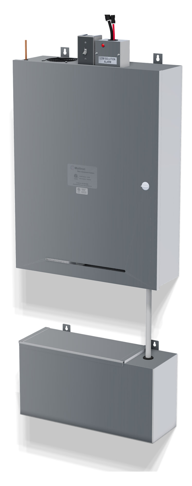

- 24 × 32 × 8 instainless steel cabinet
- 120 VAC, 20 Acircuit dedicated to MOAS
- 10 galsolution container
Contents
- 01About this manual3
- 02How MOAS works4
- 03Dimensions and what ships5
- 04Installation6
- 05Electrical and exhaust-fan interlock9
- 06Start-up14
- 07Operation and adjustment16
- 08Maintenance19
- 09Troubleshooting21
- 10Parts reference23
- 11Warranty24
- 12Start-up and owner forms25
- 13Engineer’s corner29
Where to start
Owners and kitchen staff
The daily level check, the monthly routine, what the alarm means, your warranty and the maintenance log.
Sections 08, 09, 11, 12
Installing contractors
Mounting, water, the nozzles and lines, the interlock and power, start-up, and the check-off list.
Sections 04, 05, 06, 12
Technicians and engineers
How it works, the wiring, settings and adjustments, the parts reference and copy-ready specification text.
Sections 02, 07, 10, 13
Record for this system
- Model number
- Serial number
- Ship date
- Start-up date
- Installing contractor
- Contractor’s phone
- Interlock location
- Remote alarm location

This manual online
Search, step-by-step start-up and pump-tube walkthroughs and fill-in forms, at molitron.com/products/moas/operation-maintenance. Questions, parts or Odor Neutralizer Solution: 303-969-8888 · cleanair@molitron.com.
Section 01
About this manual
Important
Installation must be performed by a qualified professional who has read and understands these instructions and is familiar with proper safety precautions; a trained HVAC technician is present for installation and start-up. Read this manual before installing or servicing the equipment.
This manual belongs to the owner of the equipment and is needed for future maintenance. Leave it with the owner when installation or service is complete; it is kept in the plastic envelope inside the cabinet door. The owner is responsible for maintaining and servicing the equipment.
On delivery
Inspect the equipment inside and out for damage. If you find any, report it to the carrier immediately and contact Molitron immediately at 303-969-8888 or cleanair@molitron.com. Check that every accessory is present and undamaged (section 03).
Who does what
- Installing contractor
- Mounts the cabinet and container, connects the water, mounts the nozzles and runs the lines, and completes the check-off list (section 12).
- Installing electrician
- Runs the dedicated circuit, and mounts and wires the exhaust-fan interlock and any remote alarm.
- Start-up
- Authorized personnel or trained kitchen staff start MOAS up, with a trained HVAC technician present, and fill in the equipment record.
- Owner and staff
- Check the solution level daily, make the monthly checks and keep the maintenance log. For maintenance or repair, authorized technicians or trained staff open the cabinet door and work on the components directly.
Listing
MOAS is ETL Listed under Intertek Report 101453585DEN-002. The report identifies UL 197 and CSA C22.2 No. 109 as the applicable standards. Listing does not establish approval of a field installation.
Performance: up to 95% odor reduction, up to 50% smoke reduction and up to 6,000 CFM per two-nozzle system. Performance varies with cooking process, hood grease-removal performance, exhaust configuration, installation, dwell time and calibration. Results are not guaranteed. Capacity is subject to project-specific configuration; smoke reduction is not a particle-filtration rating.
Section 02
How MOAS works
MOAS mixes Molitron Odor Neutralizer Solution with your building’s cold water and sends it, with compressed air, to two nozzles that mist it into your exhaust duct. The exhaust carries the mist toward the fan, giving it time to act on cooking odors. Everything that mixes and meters the solution is in one stainless steel cabinet on the wall.
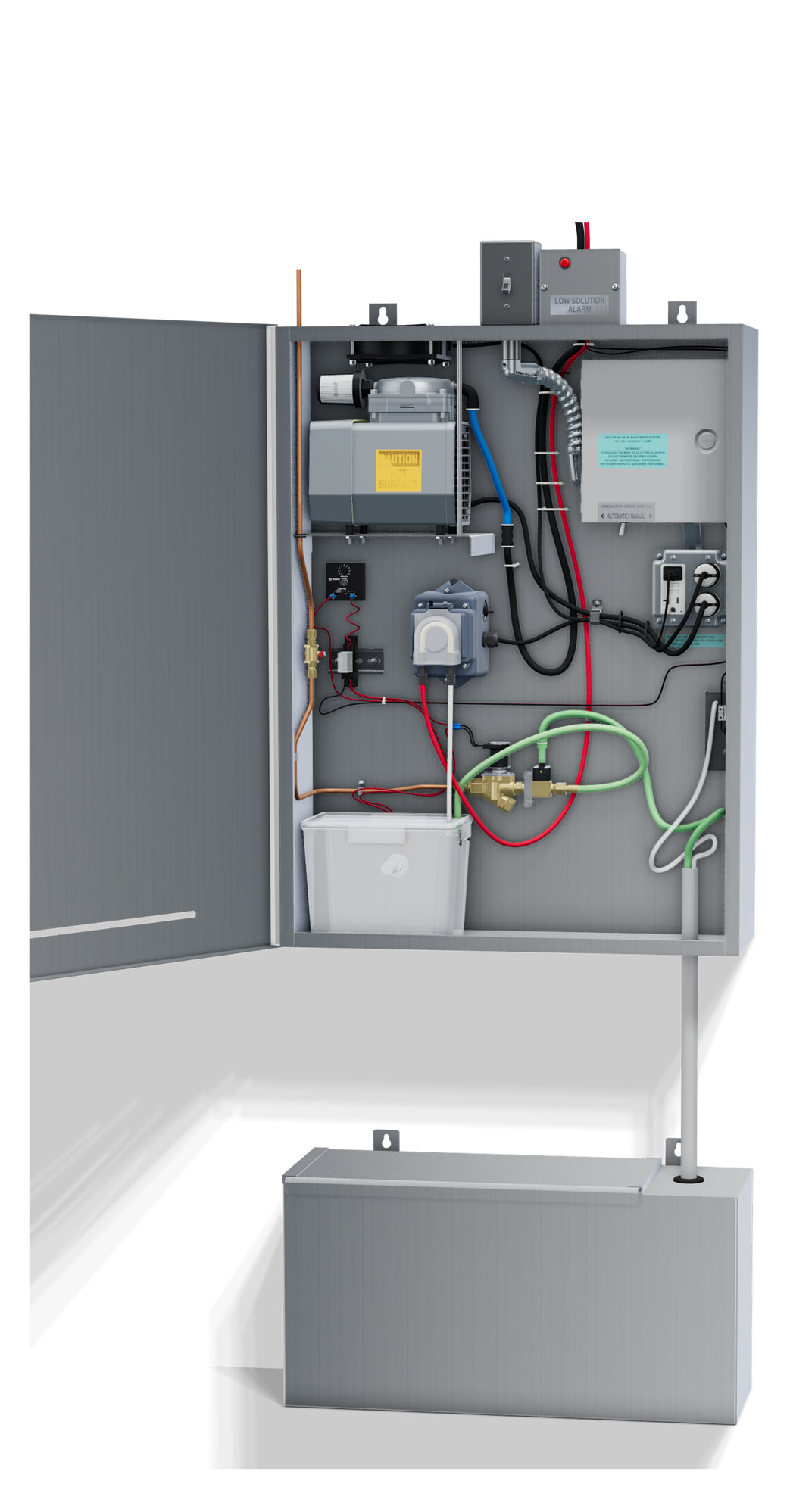
- Cold water
- Odor Neutralizer Solution
- Diluted solution
- Compressed air
Rendered from the model in Molitron’s 3D viewer, door open. Paths are illustrative.
- Cold water in
A 1/4 in copper line brings the building’s cold water in at the top and down the left side to the ball valve, the cabinet’s own shutoff.
- Solution drawn in
When the solenoid valve opens, water passing through the brass injector draws Odor Neutralizer Solution up from the container below, through a clear pickup tube and a check valve.
- Mixing container
Water and solution flow into the clear mixing container. A float switch and the refill delay timer decide when it refills.
- Air compressor
The Gast compressor sends air up the black line to the AIR port of each nozzle. The cooling fan above it carries its heat out of the top of the cabinet.
- Metering pump
The Stenner pump’s rollers squeeze its pump tube to send a measured flow of diluted solution up the red line to the LIQUID port of each nozzle.
- Out to the duct
The red and black lines leave the cabinet top for two nozzles on opposite sides of the exhaust duct, where compressed air and solution combine into a fine mist.
Three separate circuits
- Refill
- The float switch in the mixing container. When it drops, the refill relay and delay timer open the water solenoid valve after the delay; when the level rises, the float closes it.
- Low-solution alarm
- A pressure switch senses the container’s level through a separate sensing tube. When the level is low, it sounds the buzzer inside the cabinet and lights the red light on top. Like the refill, it works only while MOAS runs.
- Delivery
- The metering pump draws from the mixing container and feeds the red line to the nozzles; the compressor feeds the black line.
Section 03
Dimensions and what ships
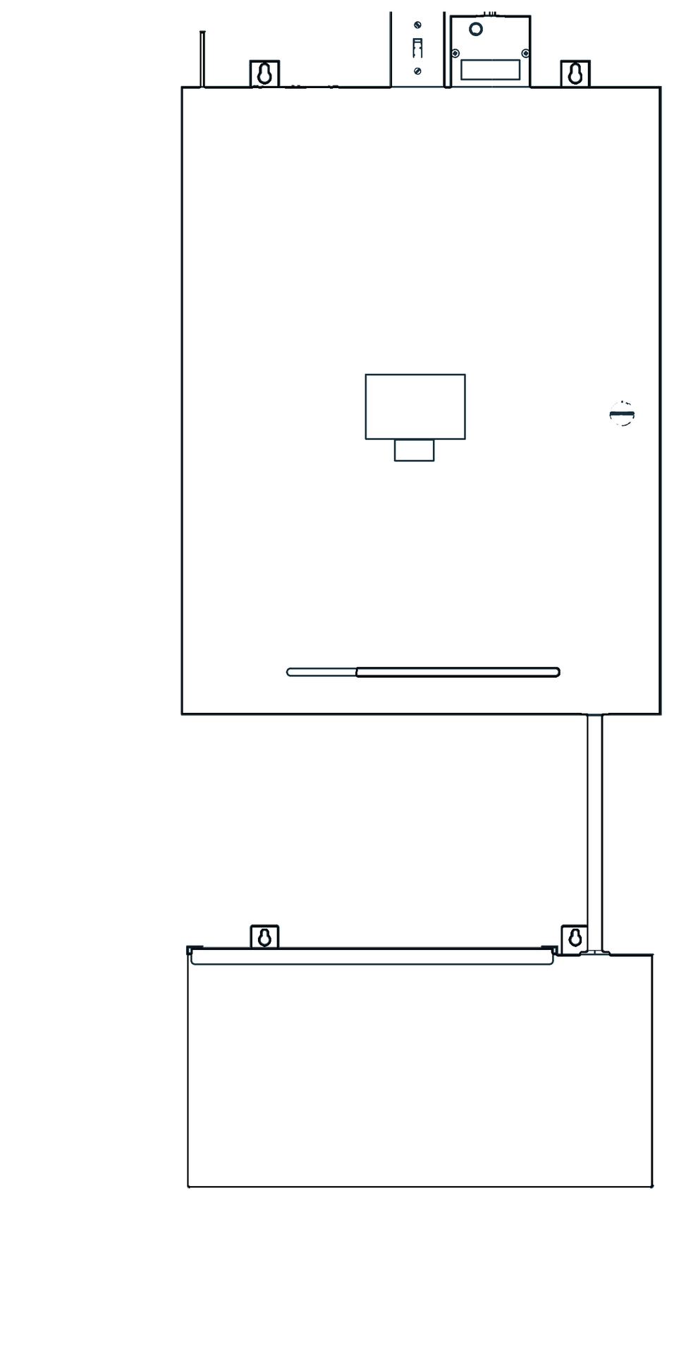
Front

Side
Additional accessories included in the shipment
- The MOAS and exhaust fan field interlock
- Red 1/4 in OD polyethylene tubing, 100 ft roll, for solution
- Black 3/8 in OD polyethylene tubing, 100 ft roll, for air
- The nozzle assembly: two atomizing nozzles with their fittings, each on a 4 in square stainless steel mounting plate
In the plastic envelope inside the cabinet door
- This installation and maintenance manual
- A spare squeeze tube for the solution pump
- A spare filter for the air compressor’s B300F intake muffler
- 3/8 in and 1/4 in tubing tees for the nozzle lines
- Weld studs with bolts, nuts, washers and lock washers, for the nozzle mounting plates
- Four 1/4 in lag bolts, for mounting the cabinet and the solution container
The stainless steel solution container ships with the cabinet. The remote low-solution alarm is optional.
Section 04
Installation
- Location
- Any convenient, ventilated indoor spot near your kitchen staff, where they can reach the solution container and hear the alarm. Never an enclosed closet without ventilation. It need not be beside the cooking line.
- Mounting
- Hang the cabinet on wall studs, 16 in centers, through the two keyhole tabs at the top of its back, with the 1/4 in lag bolts supplied. Mount the solution container on the wall below it. Final support and anchorage are project-specific.
- Clearance
- Keep the cooling-fan opening on top clear, and leave room to open the door and slide the solution container lid forward to add solution.
- Finished spaces
- Where the cabinet is above or near a finished space, protect that space from water damage in case of a plumbing leak or equipment failure.
- Cold water
- A 1/4 in copper cold-water supply to the connection on the cabinet top, 80 PSI maximum, with enough pressure for the injector to draw solution. Fit a building shutoff valve; the ball valve inside the cabinet is MOAS’s own shutoff.
- Backflow protection
- A white check valve above the injector lets solution flow one way only, so the mixing container’s contents cannot siphon back down the pickup tube into the 10-gallon solution container.
- Power
- A 120 VAC, 20 A circuit dedicated to MOAS, in conduit from the electrical panel through the MOAS exhaust-fan interlock to the cabinet. Everything inside the cabinet is factory wired. See section 05.
Mounting the nozzles
Each nozzle comes attached to a 4 in square stainless steel plate with eight holes. The plate mounts on the outside of the exhaust duct, over a 1-1/2 in hole the contractor drills, and the nozzle sprays into the exhaust stream.
- Choose the spot
Two nozzles go on opposite sides of the exhaust duct, as close to the odor source as practical, with at least 10 ft of duct between them and the exhaust discharge so the mist has time to act. Leave each nozzle’s rear cleaning button within reach for the monthly cleaning.
- Weld the studs
Weld the eight stainless steel studs supplied to the outside of the duct wall, to match the eight holes in the 4 in square mounting plate.
- Drill the hole
With the plate in place over the studs, mark the centre of the plate. Remove the plate and drill a 1-1/2 in hole through the duct wall at the mark.
- Mount the nozzle
Fit the plate, with its nozzle, over the studs so the nozzle sprays through the hole into the duct. Secure it with the nuts, washers and lock washers supplied.
- Connect the lines
Push the black 3/8 in air line into the port marked AIR and the red 1/4 in solution line into the port marked LIQUID. The nozzle and plate come off the duct as one piece if they ever need service.
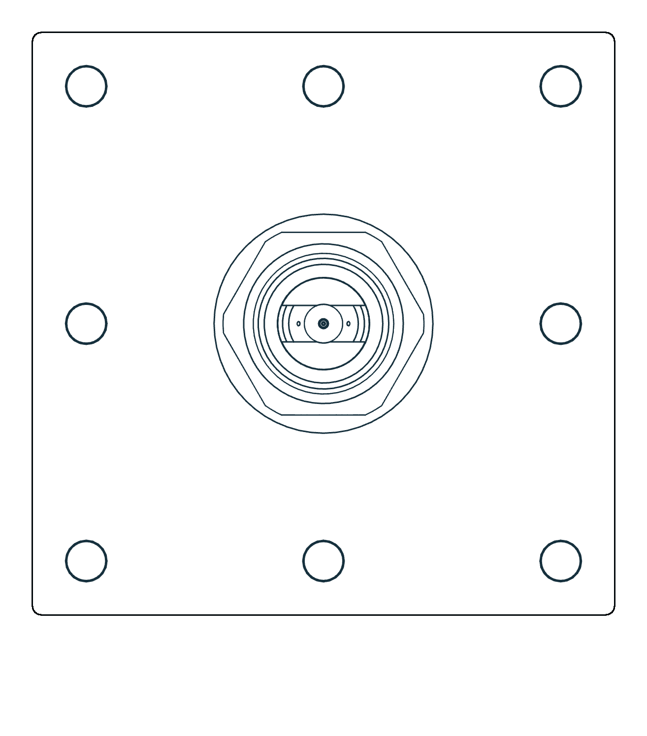
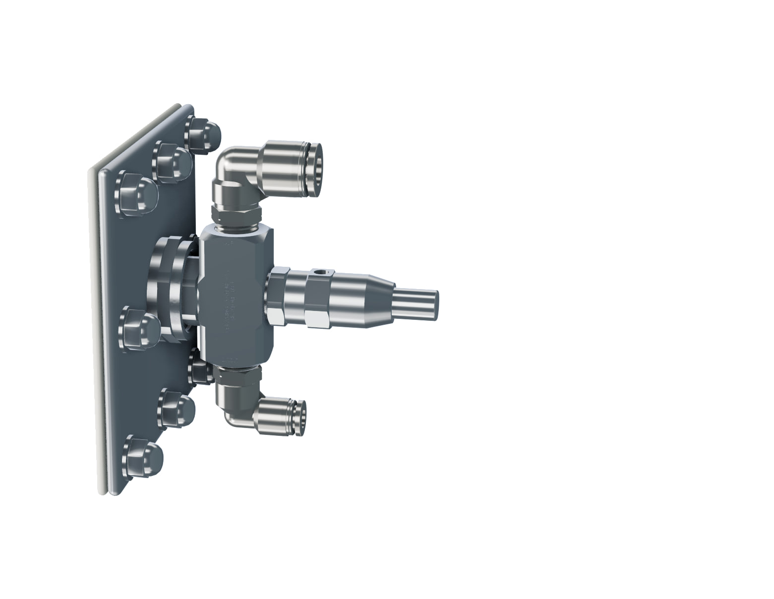
A nozzle as it mounts on the duct, from the 3D viewer’s model.
Running the lines
- Air
- Black 3/8 in OD tubing, from the cabinet top to a 3/8 in tee, then a branch to the AIR port of each nozzle.
- Solution
- Red 1/4 in OD tubing, from the cabinet top to a 1/4 in tee, then a branch to the LIQUID port of each nozzle.
- Length
- Up to 100 ft for each routed path from the cabinet, through its tee, to a nozzle. Keep matching branches close in length, comparing the two air branches with each other and the two solution branches with each other. Confirm routing with Molitron.
- Conduit
- Running both lines in 1 in conduit is recommended to protect them. It is not a universal code requirement.
- Container tubes
- The clear pickup and pressure-sensing tubes run inside a 1/2 in PVC tube from the bottom of the cabinet down into the solution container, through its fixed top panel. Keep them in their installed positions.
Section 05
Electrical and exhaust-fan interlock
Danger: risk of electric shock
Disconnect power before wiring or servicing. The interlock and the cabinet carry 120 VAC; exhaust-fan circuits can carry up to 277 V.
MOAS needs a 120 VAC, 20 A circuit dedicated to it, run in conduit from the electrical panel through the MOAS exhaust-fan interlock to the power switch on top of the cabinet. The exhaust fan has its own, separate connection to the interlock. Everything inside the cabinet is factory wired. The listed equipment rating, 120 V, 3.5 A, 60 Hz, is a separate value from the dedicated-circuit requirement.
Exhaust-fan interlock
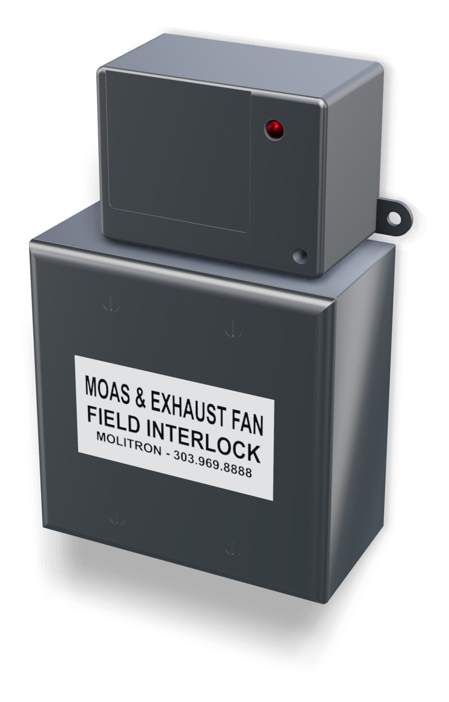
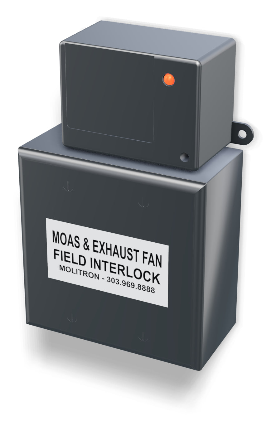
The relay keeps MOAS from running whenever the exhaust fan is off. It is energized by the exhaust fan’s power: when the fan is on, the relay closes and completes the MOAS circuit from the building panel to the cabinet. MOAS does not power the exhaust fan. It measures 4 W × 7 H × 2.5 D in.
The red light. The small red light on the relay on top of the interlock comes on whenever the exhaust fan’s power energizes the relay. Light on: the fan is on and the interlock is letting power through to MOAS. Light off: the relay is not energized, so MOAS cannot run.
- Hot, MOAS circuit
- Neutral, MOAS circuit
- Exhaust-fan power to the coil (dashed: 208–277 V fans)
- Relay leads
Coil leads: the fan’s power
| Lead | Rating | Use |
|---|---|---|
| White/brown | 208–277 VAC | Exhaust-fan power, on 208–277 V fans: one phase |
| White/black | 120 VAC | Exhaust-fan power, preferred: 120 V from the hood switch |
| White/blue | 24 VAC/DC | Exhaust-fan control power, 24 V |
| White/yellow | Common | Common for whichever coil lead is used |
Contacts: the MOAS circuit
| Lead | Contact | Use |
|---|---|---|
| Yellow | Common | LINE MOAS: the hot (black) wire of the 20 A MOAS circuit from the building panel |
| Orange | Normally open | LOAD MOAS: the hot wire on to the MOAS cabinet |
| Blue | Normally closed | Not used |
Powering the coil
- Preferably, use the 120 V power and common from the hood switch that energizes the exhaust fan’s magnetic motor starter coil (white/black and white/yellow leads).
- For 208–277 V exhaust fans, use one of the phases and the common (white/brown and white/yellow leads).
Remote low-solution alarm (optional)
- Size
- 3 W × 5 H × 3 D in
- What it does
- Repeats the cabinet’s low-solution alarm where staff can see it. Its faceplate carries a red light, a speaker grille and two contacts marked Touch to silence.
- Power
- 24 V, from the cabinet’s low-solution alarm terminals, where it shares the red light’s power.
- Cable
- 18/2 shielded security cable from the cabinet to the alarm.
- Location
- Mounted and wired by the installing electrician, somewhere staff can see it while they work.
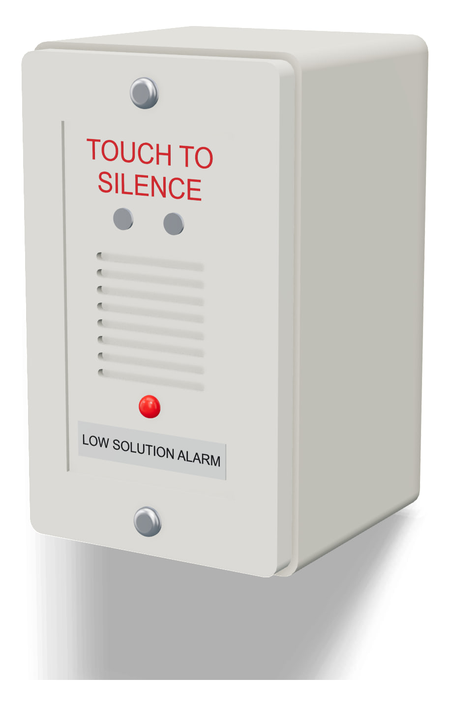
- Touch-to-silence contacts
- Speaker grille
- Red light
- Label
Rendered from Molitron’s model of the remote alarm.
Inside the cabinet
Logic diagram
- 120 VAC
- 24 VAC control
Schematic
- Black (BK)
- White (W)
- Ground (GRD)
- Red, 24 VAC
Refill sequence. When the float switch is down, the refill relay is not energized, and the water solenoid valve opens once the delay timer has timed out. When the water raises the float, the relay is energized and the solenoid valve closes. The delay is adjustable from 30 seconds to 8 minutes and is set to 8 minutes.
Section 06
Start-up
Before start-up, check the installation
- The MOAS cabinet is securely mounted in a ventilated location, close enough to the kitchen staff that they can hear its alarm.
- The 10-gallon solution container is securely mounted on the wall below the cabinet.
- The MOAS and exhaust fan field interlock is mounted and wired to both the exhaust fan and MOAS, and the 120 VAC, 20 A circuit dedicated to MOAS runs through it to the power switch on top of the cabinet.
- The 1/4 in copper cold-water supply is connected, and the building’s shutoff valve is open.
- Both nozzles are mounted in the exhaust duct where they can be reached for monthly maintenance.
- The black 3/8 in air line and the red 1/4 in solution line are connected to the couplings on top of the cabinet and to the tees that supply the nozzles, with equal lengths of tubing from each tee to its two nozzles.
Start-up follows these 13 steps, in this order. The parts are pictured in section 10.
- Check the starting positions
With the cabinet door open and the power still off, check that:
- The power switch on top of the cabinet is OFF.
- The operation mode switch is on Manual.
- The refill delay timer knob is set to 8 minutes.
- The pump speed control is off, turned fully counterclockwise.
- Nothing blocks the cooling fan’s guard at the top of the cabinet, above the compressor.
- Prepare the solution container
A 1/2 in PVC tube carries two clear tubes from the bottom of the cabinet down into the solution container. Check that:
- The PVC tube is inserted through the bottom of the cabinet into the solution container.
- The 3/8 in clear tube is connected to the white check valve on the injector.
- The 1/4 in clear tube is pushed onto the black nipple of the low-solution pressure switch, with the snap hose clamp closed over it. Connect and clamp it before the tube goes down into the solution, or the alarm will sound when MOAS is powered on.
- The solution container holds at least 4 gallons of Molitron Odor Neutralizer Solution. Slide its lid forward to fill it.
- Free the float switch
Remove the rubber band that holds the float switch in the mixing container for shipping.
- Unplug the three cords
In the receptacle box inside the cabinet, unplug the cords for the solution pump, the air compressor and the cooling fan. This keeps the air compressor quiet while you set up, and leaves the GFCI receptacle’s red RESET button easy to reach.
- Power on
With the exhaust fan running, so the interlock lets power through, turn the power switch on top of the cabinet to the ON position. The SmartRelay display lights up; the air compressor stays off until its cord goes back in. If the alarm sounds, turn the power switch off and see Troubleshooting, section 09, to clear it.
- Turn on the water
Turn the red handle of the water ball valve, on the left side inside the cabinet, to its vertical ON position.
- Fill the mixing container
Run the first fill with a short refill delay, then set the delay back:
- Turn the refill delay timer knob to 30 seconds.
- Within 30 seconds, the water solenoid valve opens and water runs through the injector into the mixing container. You should see Odor Neutralizer Solution drawn up the 3/8 in tube from the solution container below.
- Turn the timer knob back to 8 minutes. Delaying each refill by 8 minutes gives better control over the solution’s concentration.
- Start
Make sure the SmartRelay’s program is running. Press Esc, and the menu shows Stop, Program, Setup, Network and Diagnostics. If it shows Start instead of Stop, select Start and press OK.
- Set the clock
The SmartRelay display shows the time and date in 24-hour time. Press Esc to see the menu:
- Select Setup with the down arrow and press OK.
- Select Clock, and set the time, in 24-hour time, and the date with the arrow buttons.
- Keep pressing OK until you return to the time and date display.
- Run periods
When the switch is in the Automatic position, MOAS runs only during the run periods (cooking periods) set on the SmartRelay, and only while the exhaust fan runs. Set up to three periods. The example on the left is the factory default; change the times to match your cooking hours.
- Press Esc, then select Program, Set Parameter, Run Periods.
- For each period, toggle its days (D1, D2, D3) on or off with the arrow buttons, and set its start (On) and stop (Off) times in 24-hour time.
- Leave Pulse Off.
- Come back to this screen whenever your cooking hours change.
D1=MTWTFSS
On1=10:00
Off1=14:00
D2=MTWTFSS
On2=17:00
Off2=20:00
D3=MTWTFSS
On3=00:00
Off3=00:00
Pulse=Off
- D1
- Days for period 1: toggle each day on or off with the arrows
- On1
- Start, 24-hour time
- Off1
- Stop
- D2
- Days for period 2
- On2
- Start
- Off2
- Stop
- D3
- Period 3, not set
- Pulse
- Do not change: Pulse must stay Off
An example: a lunch and a dinner period. Set your own cooking hours. Leave Pulse Off.
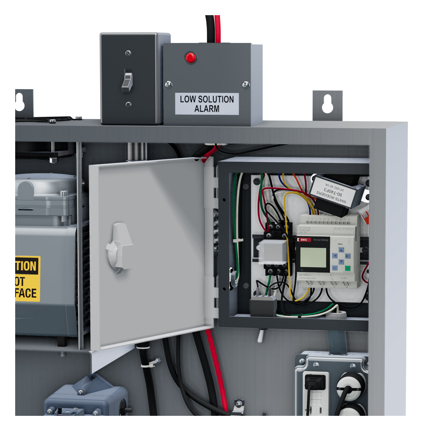
The control enclosure open on the SmartRelay.
- Reset the GFCI and plug in the cords
On Manual, with the power switch on, the GFCI receptacle has power.
- Press the red RESET button on the GFCI receptacle.
- Plug in the cords for the solution pump, the air compressor and the cooling fan.
- The air compressor and the cooling fan above it start. The pump stays off until its speed control is turned up.
- Start the solution pump
Turn the pump speed control clockwise to 100. Through the pump head’s clear cover, watch the rollers turn around the squeeze tube: the pump draws mixed solution from the mixing container up the clear 1/4 in tube and sends it up the red 1/4 in line to the nozzles in the duct. MOAS is in full operation as soon as solution and air reach the nozzles.
- Check the nozzles and switch to Automatic
Finish the start-up:
- Check that both nozzles in the duct are misting.
- Return the operation mode switch to Automatic, where it stays in service. MOAS now runs during the cooking periods, whenever the exhaust fan runs.
- Record the start-up settings in the equipment record, section 12.
Section 07
Operation and adjustment
The cooking periods are set in start-up step 10, and changed there whenever your hours change. These are the other settings a technician can change.
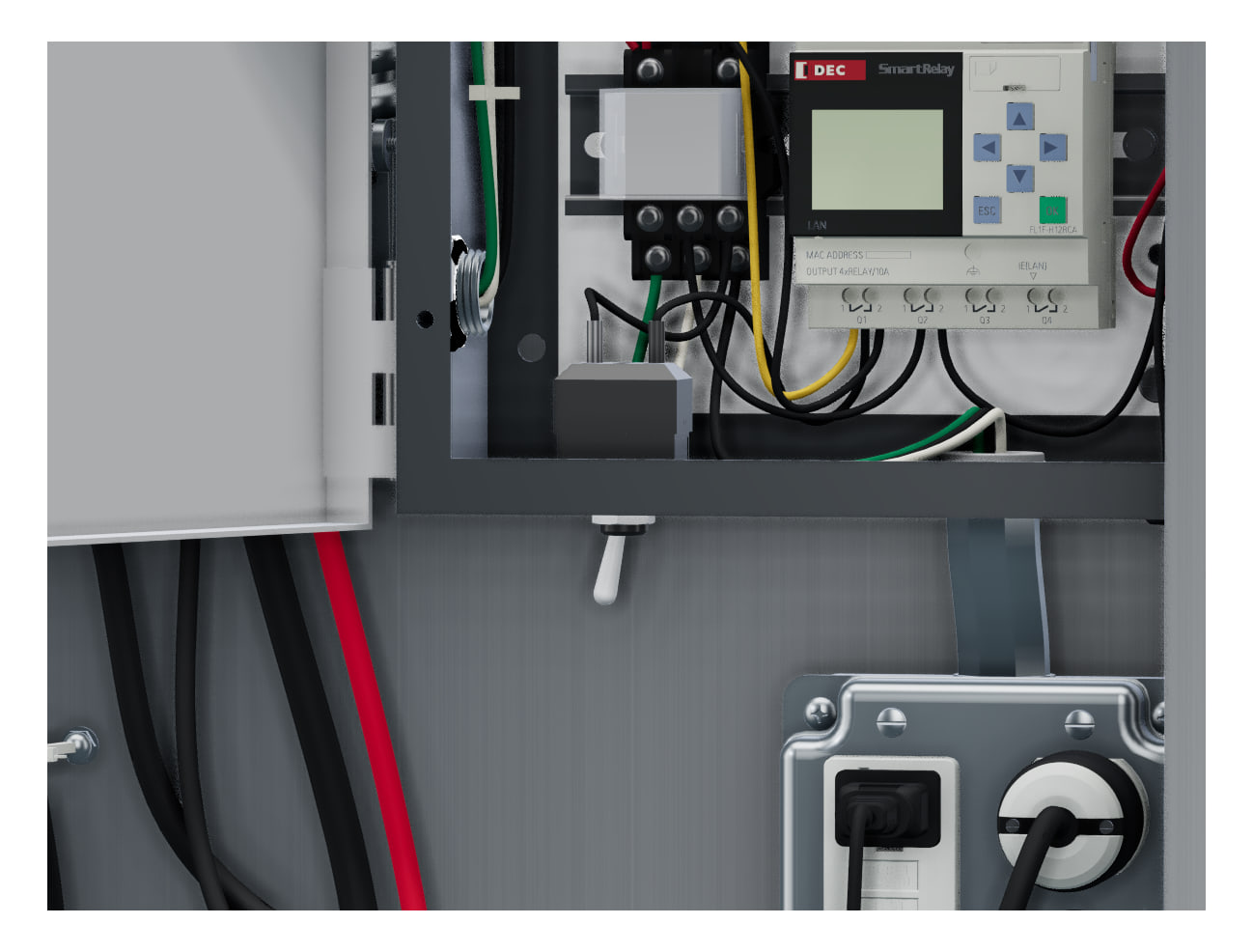
Operation mode switch
On Automatic, the SmartRelay runs MOAS during the cooking periods. On Manual, the schedule is bypassed and MOAS has continuous power, for testing and maintenance. In both modes the exhaust-fan interlock keeps MOAS off whenever the fan is off. Leave it on Automatic in service.
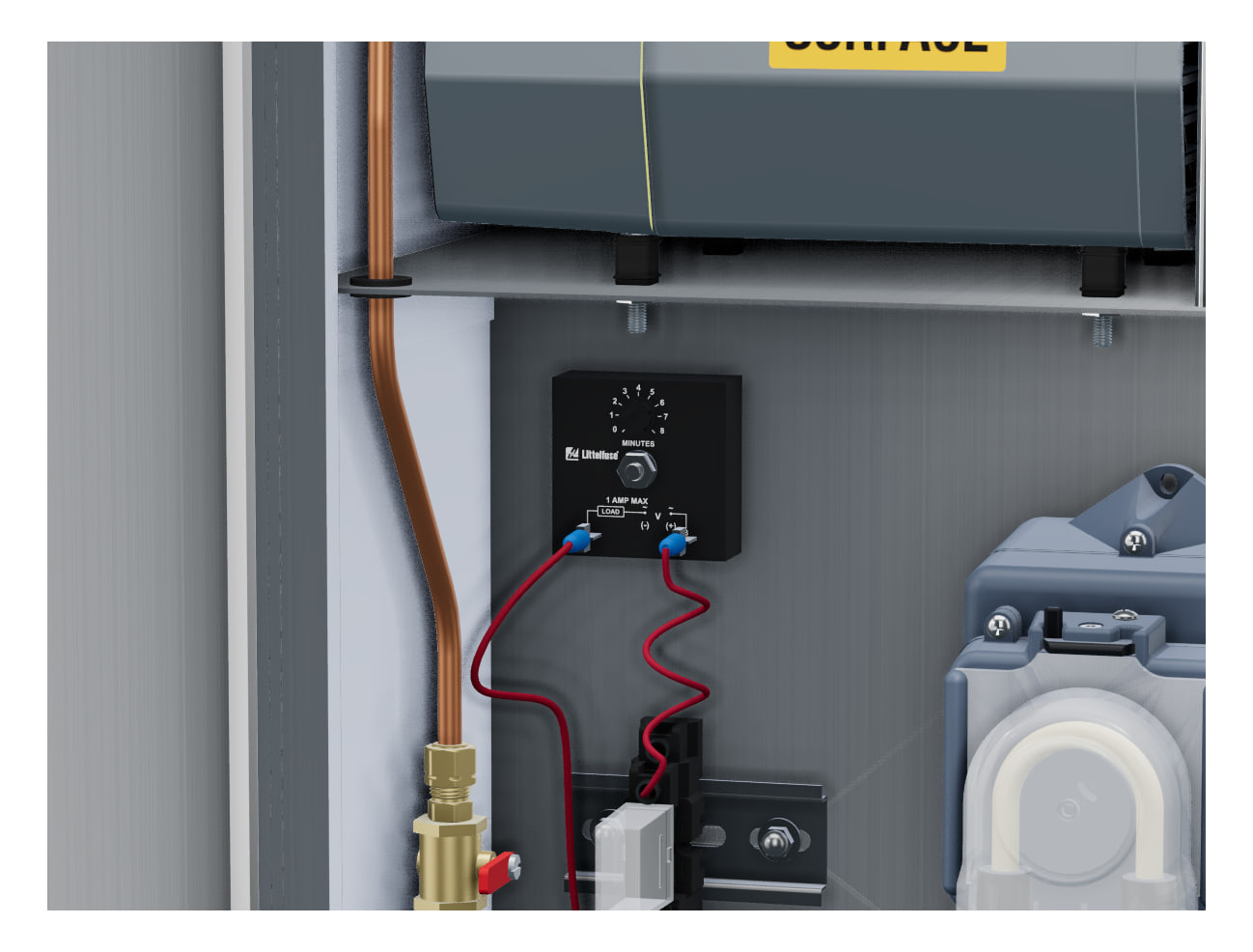
Refill delay timer
The square black Littelfuse solid-state timer, 24 V, on the left wall above the refill relay. It waits before opening the water solenoid valve, so the mixing container refills less often and mixes better. Adjustable from 30 seconds to 8 minutes; set to 8 minutes. If the mixing container needs to refill more often, set a shorter delay.
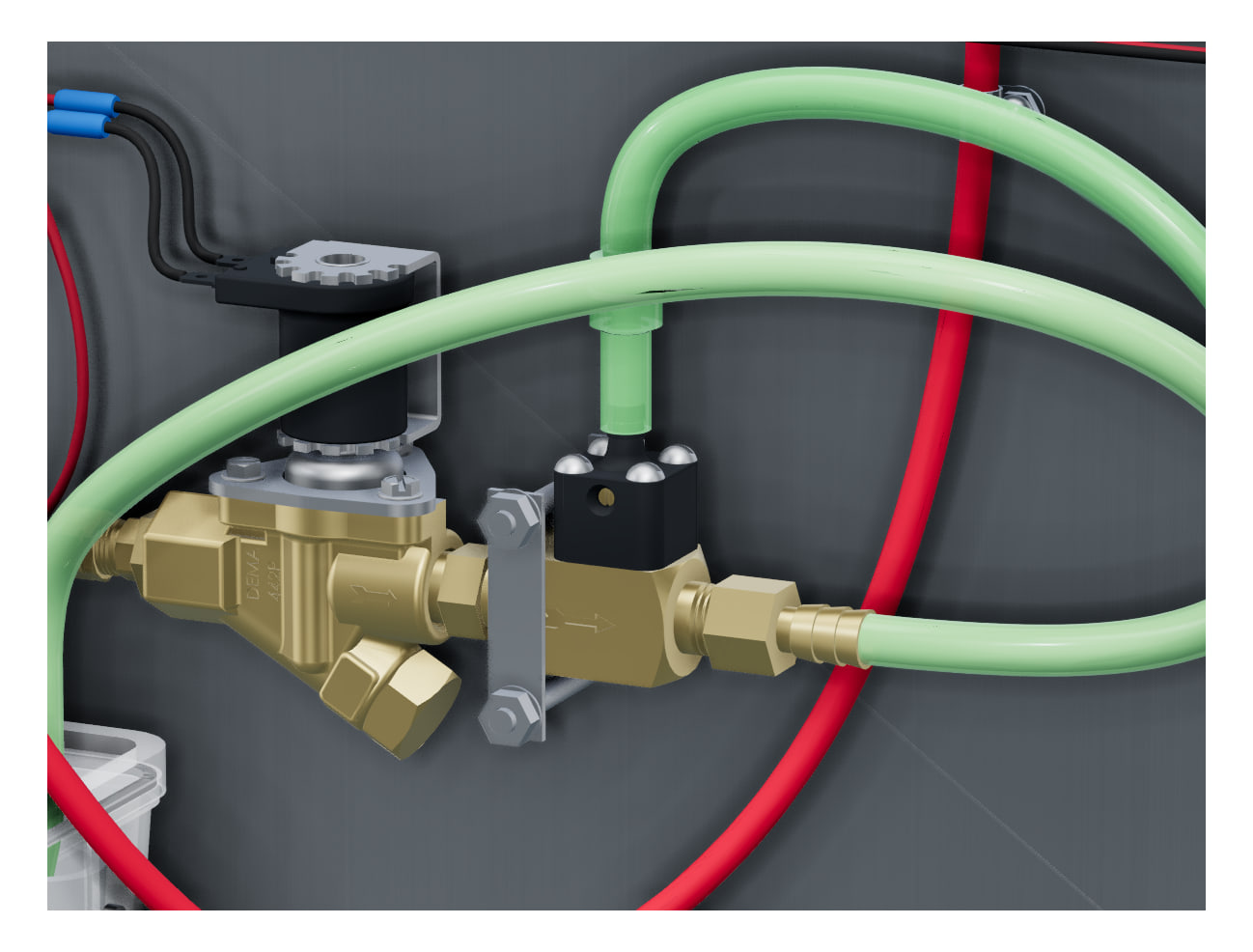
Injector volume screw
The set screw on the front of the injector controls how much Odor Neutralizer Solution is drawn in. From the factory it is normally set one half turn counterclockwise from fully closed, which uses approximately 40 fl oz of water and 1 fl oz of solution per hour. To change the concentration, adjust the pump speed first. If that does not give the results you want, use a small flathead screwdriver: turn the screw counterclockwise (left) to increase the concentration, or clockwise (right) to decrease it, a quarter turn at a time, checking the results between turns. Do not unscrew it all the way, or it will fall out. Check the color of the solution in the mixing container and the odor at the exhaust, and record any change in the maintenance log.
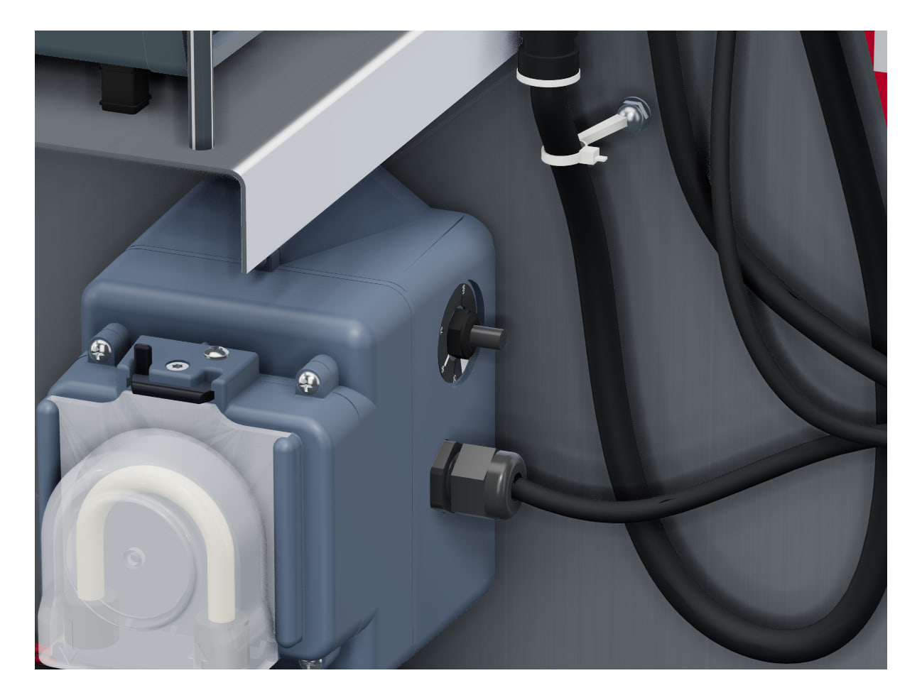
Pump speed control
The potentiometer (speed control) on the side of the Stenner pump sets its output: fully counterclockwise is off, and turning clockwise raises it gradually to 100% at fully clockwise. A raised line on its edge shows the setting; graduations are approximate. MOAS starts at 100. If the solution runs out too fast, turn it counterclockwise about a quarter, to 75, and check that both nozzles still mist. Record the start-up setting in the equipment record, and any change in the maintenance log.
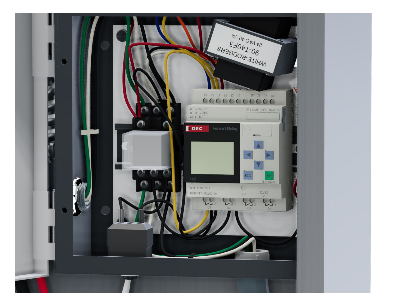
SmartRelay clock
It keeps time for several days without power. Check it monthly and after any long power outage, and reset it under Setup, Clock if needed.
Section 08
Maintenance
Every day
- Check the solution level. When MOAS is working, it drops a little each day of use.
- Refill only with Molitron Odor Neutralizer Solution. Slide the lid forward to check or refill; the tubes stay in place. Refill right away when the alarm sounds, at approximately two gallons remaining.
Every month, with MOAS running
- Clean the nozzles
With MOAS and the exhaust fan running, press and release the rear cleaning button on each nozzle several times. This keeps grease buildup from obstructing the nozzle tips. While you are there, check the tubing fittings at each nozzle for leaks.
- Check for leaks
Check every tubing and plumbing connection, from the lines to the nozzles to the copper water line at the cabinet.
- Test the alarm
Slowly raise the 1/2 in PVC tube in the solution container until the buzzer sounds and the red light illuminates, then lower it back to the bottom of the container.
- Check the clock
Check that the SmartRelay shows the correct time.
- Check the level is dropping
If the solution level has stopped dropping, check that the pump tube is still moving liquid, and replace it if it is worn (below).
Every month, shut down
- Shut down
Before any service except the monthly nozzle buttons, turn the cabinet power switch off and close the cabinet water valve.
- Open the muffler
Find the B300F intake muffler at the top left of the air compressor. Twist its cover a quarter turn and pull it off.
- Replace the filter
Replace the fabric filter with the spare from the plastic envelope inside the cabinet door, then order a new spare from Molitron. If there is no spare, rinse the filter and let it dry completely before refitting it.
- Refit and restart
Refit the filter and the cover. Open the cabinet water valve and turn the power switch back on. Record the visit in the maintenance log, in the plastic envelope inside the cabinet door.
Record each month in the maintenance log (section 12).
Replacing the pump tube
Before service
Before any service except the monthly nozzle buttons, turn the cabinet power switch off and close the cabinet water valve. The cabinet carries 120 VAC: always unplug the pump before working on it.
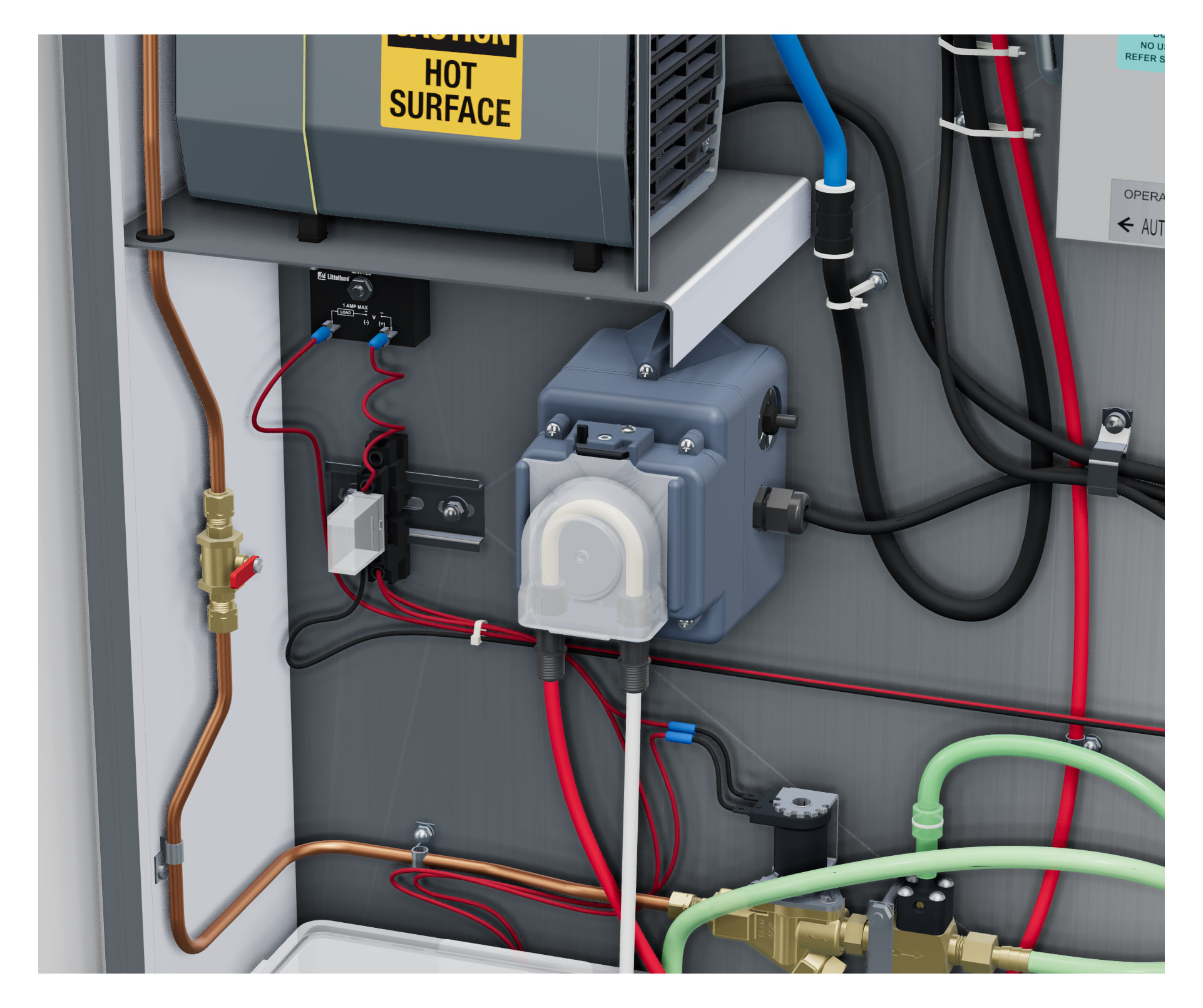
The Stenner pump, from the 3D viewer’s model. The pump tube is the U-shaped tube under the pump head’s clear cover.
If the pump tube is worn, or the solution level has stopped dropping, replace the tube with the spare from the plastic envelope inside the cabinet door. Follow Stenner’s own Tube Replacement instructions, which start on page 21 of the Stenner ECON FX and VX instructions (stenner.com). They come from the pump’s manufacturer, so you work from its current steps, and they include the cautions to read before you start.
Open the water valve and turn the power back on when you are done.
Section 09
Troubleshooting
Before you call for service. Before any service except the monthly nozzle buttons, turn the cabinet power switch off and close the cabinet water valve.
The buzzer is sounding and the red light is on
- The solution container is low.
- Refill it with Molitron Odor Neutralizer Solution.
- It keeps sounding after you refill.
- Liquid is trapped in the sensing tube. Pull the clear 1/4 in sensing tube off the black pressure-switch nipple. Lift the 1/2 in PVC tube just above the solution container (it does not need to come out of the cabinet) and shake or tap it to clear the liquid, or blow through the top end of the clear tube (the solution is non-toxic). Reconnect the clear tube to the nipple before you lower the PVC tube back in, then set it on the bottom of the container without forcing it.
The mixing container is not filling with water
- The refill delay has not run out.
- The solenoid valve opens only after the timer’s delay, set to 8 minutes. Wait out the delay. (section 07)
- The cabinet water valve is closed.
- Open the red-handled ball valve inside the cabinet. (section 10)
- The building water is off or its pressure is low.
- Check that the building supply is on and reaching the cabinet’s valve.
- The solenoid valve has failed.
- Replace the solenoid valve. (section 10)
Little or no solution is reaching the mixing container
- The refill delay is set too short.
- Set the timer back to 8 minutes, which mixes best. (section 07)
- The injector needs adjusting.
- Adjust the injector’s volume screw. (section 07)
- The check valve is stuck.
- Remove and clear the check valve above the injector, in the clear pickup tubing. (section 10)
- The building water pressure is low.
- There must be enough pressure for the injector to draw solution up from the container.
- The injector has failed.
- Replace the injector. (section 10)
MOAS runs while the exhaust fan is off
- The exhaust-fan interlock is missing, wired incorrectly or has failed.
- The interlock keeps MOAS off whenever the fan is off, in Automatic and Manual alike. Have an electrician check the interlock’s wiring, and install or replace it. (section 05)
MOAS is not running while the exhaust fan is on
- It is outside the cooking periods.
- On Automatic, MOAS runs only during the run periods. Set them to match your cooking hours. (section 07)
- No power.
- Check that the power switch on top of the cabinet is on, and reset the GFCI receptacle. (section 10)
The pump, compressor or fan has no power
- The GFCI receptacle has tripped.
- Unplug the cords and press the reset button on the receptacle, then plug them back in. (section 10)
- The GFCI receptacle has failed.
- Replace the GFCI receptacle. (section 10)
The mixing container is overflowing
- The float switch is stuck or has failed.
- Check that the float’s lever moves freely; replace the float switch if it does not. (section 10)
The nozzles are not misting
- The air compressor is not running.
- Check it has power (reset the GFCI), that the cooling fan above it is running with its opening clear, and that it is not overheating. Replace the muffler filter. (section 08)
- The pump is not running.
- Check it has power, and reset the GFCI receptacle. (section 10)
- The pump tube is worn.
- Check the tube and replace it. (section 08)
- The nozzles are clogged.
- Press each nozzle’s rear cleaning button several times, with MOAS and the fan running. (section 08)
Still not right? Call Molitron: 303-969-8888 · cleanair@molitron.com.
Section 10
Parts reference
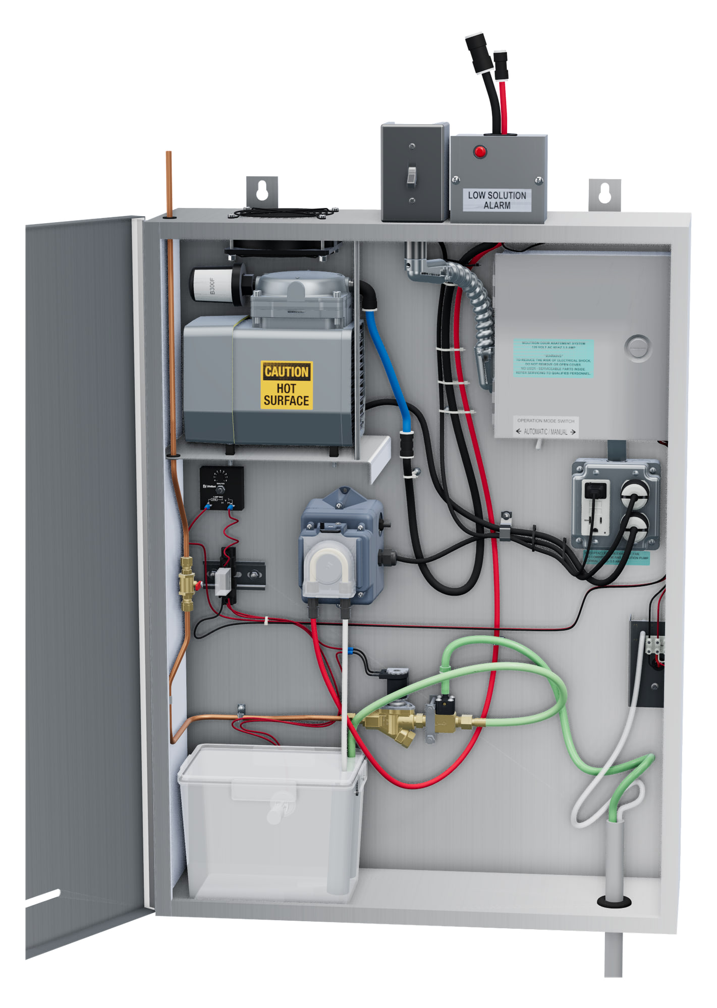
The cabinet with its door open, from the 3D viewer’s model.
- Cooling fan
Dayton axial fan, 120 VAC, in the top of the cabinet.
- Air compressor
Gast, 1/3 hp, 120 VAC, on rubber vibration isolators.
- Intake muffler
B300F, with a washable fabric filter.
- Refill delay timer
Littelfuse solid-state timer, 24 V, 30 s to 8 min, set to 8 min.
- Refill relay
IDEC SPDT relay, 24 VAC coil, with LED.
- Metering pump
Stenner variable-speed peristaltic pump, 120 VAC.
- Water ball valve
The cabinet’s own cold-water shutoff, red handle.
- Water solenoid valve
1/4 in, normally closed, 24 VAC.
- Injector
Brass, 1/4 in, with the volume screw on its front.
- Check valve
3/8 in, above the injector, in the clear pickup tubing.
- Mixing container
Clear, with the float switch.
- Control enclosure
The IDEC SmartRelay (24 VAC), the 3PDT relay (24 VAC coil), the 120/24 VAC transformer and the operation mode switch.
- Receptacle box
4 × 4 in box with the GFCI receptacle for the compressor, pump and fan cords.
- Low-solution alarm light
The red light in the box on top of the cabinet.
- Power switch
On top of the cabinet, 120 VAC. Everything inside the cabinet is factory wired to it.
- Low-solution pressure switch
At the very top left of the panel on the right wall of the cabinet, 24 VAC, with its buzzer inside the cabinet. Only its front shows: the black nipple, with the clear 1/4 in sensing tube connected to it.
Not in the picture
- Pump tube
- A spare squeeze tube ships in the plastic envelope inside the cabinet door.
Order replacement parts and Odor Neutralizer Solution from Molitron: 303-969-8888 · cleanair@molitron.com.
Section 11
Warranty
MOAS and its component parts are warranted to be free from defects in material and workmanship for 12 months from the date of shipment. The component parts are:
- Electrical control panel
- Air compressor
- Solution metering pump
- Liquid level switch
- Miscellaneous electrical components
- What’s covered
- Should any part of the equipment prove defective in material or workmanship within the 12-month warranty period, upon examination by the factory, that part will be repaired or replaced by the factory at no charge, for parts only. All labor costs incurred in connection with the repair or replacement are not included. The factory does not accept returns of Molitron products.
- Not covered
- Parts damaged by the freight carrier between the factory and the destination, or by the installing contractor. The factory is not liable for incidental and consequential losses and damages potentially attributable to malfunctioning equipment.
- The warranty does not apply if
- MOAS is not installed by a qualified installer according to the factory’s installation instructions shipped with the product.
- MOAS is not installed in accordance with federal, state and local codes and regulations.
- MOAS is misused or neglected.
- Factory-authorized parts and Molitron Odor Neutralizer Solution are not used.
- MOAS is not operated within its published capacity.
- The invoice is not paid within the terms of the sales agreement.
The warranty is activated once the owner’s acknowledgement (section 12) is signed and returned to the factory. Email a signed copy to cleanair@molitron.com.
Section 12
Start-up and owner forms
Complete the check-off list before start-up and the equipment record at start-up. Email the signed owner’s acknowledgement to cleanair@molitron.com to activate the warranty. Keep the maintenance log with this manual.
Section 13
Engineer’s corner
Copy-ready text for a project specification, written only from this manual. Confirm details with Molitron for your project.
MOAS — Kitchen exhaust odor abatement system

1. Manufacturer: Molitron Company Inc. Molitron Odor Abatement System (MOAS), with standard external solution container and two atomizing nozzles.
2. Listing: ETL Listed for the United States and Canada, Intertek Report 101453585DEN-002 (UL 197, CSA C22.2 No. 109). Commercial, indoor-use, permanently connected equipment; listed rating 120 V, 3.5 A, 60 Hz.
3. Performance: up to 95% odor reduction, up to 50% smoke reduction, up to 6,000 CFM per two-nozzle system. Performance varies with cooking process, hood grease-removal performance, exhaust configuration, installation, dwell time and calibration; results are not guaranteed.
4. Cabinet: 18-gauge stainless steel, 24 W x 32 H x 8 D in, approximately 100 lb, wall-mounted on 16 in centers through two keyhole hanging tabs; ventilated indoor location, not an enclosed closet.
5. Solution container: 16-gauge stainless steel, 24 W x 12 H x 8 D in, up to 10 gallons of Molitron Odor Neutralizer Solution, wall-mounted below the cabinet, with sliding fill lid. Low-solution alarm below approximately 2 gallons: buzzer inside the cabinet and red light on top; optional 24 V remote low-solution alarm.
6. Equipment: cold-water solenoid valve and injector with refill delay timer (30 s to 8 min, set to 8 min) and float-controlled mixing container; Stenner variable-speed peristaltic metering pump; Gast air compressor; IDEC SmartRelay schedule control with Automatic/Manual operation mode switch; cooling fan.
7. Nozzles: two atomizing nozzles on 4 in square stainless steel plates, mounted on opposite sides of the exhaust duct over 1-1/2 in holes, at least 10 ft of duct upstream of the exhaust discharge.
8. Lines: black 3/8 in OD air and red 1/4 in OD solution polyethylene tubing, each through a tee to both nozzles; up to 100 ft per cabinet-to-tee-to-nozzle path, matching branches close in length; 1 in conduit recommended.
9. Utilities: 120 VAC, 20 A circuit dedicated to MOAS through the MOAS exhaust-fan interlock (supplied), which prevents operation whenever the exhaust fan is off; 1/4 in copper cold-water supply, 80 PSI maximum, with building shutoff valve; backflow protection provided by Molitron.
10. Maintenance: daily solution-level check; monthly nozzle cleaning, leak check, alarm test, clock check and intake-muffler filter service.
The online installation planning guide: molitron.com/products/moas/installation-planning. For drawings or project questions: 303-969-8888 · cleanair@molitron.com.
MOAS Installation, Operation & Maintenance Manual, Version 2.0, October 2026; supersedes the manual revised 8/2024. Molitron Company Inc · 303-969-8888 · cleanair@molitron.com · molitron.com. Specifications may change; confirm current details with Molitron.